Matt Blackshaw
Week 8: Input Devices
Touchpad
The idea
This week I made a capacitive touchpad with an ATTiny44 micro controller which measures input voltage on a number of copper pads using step response.
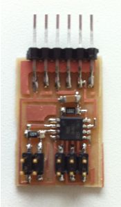
Testing step response
To fully understand step response and its precision I milled and stuffed Neil's demo step response circuit and ran it with the code he provided. Unfortunately the first time I programmed the micro controller I set the low fuse to 0x7E telling it to use an external clock (ooops!)... Because the circuit didn't have one, the chip was rendered lifeless. David Mellis suggested hooking up an external clock to the correct pins, but I instead opted for replacing the ATTiny45 through unsoldering (hint: use a hot air gun , they're AMAZING).
Circuit design
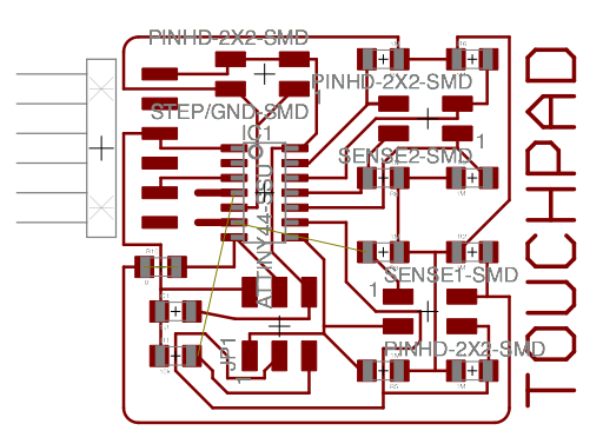
Once I had a grasp of step response I designed my own circuit which had 8 step response inputs. I used an ATTiny44 because it has 8 pins hooked up to the analog to digital converter through an on-chip analog multiplexer. I thought that the ATMega168 would offer even more analog input pins, but it unfortunately does not... To get more pins I would've had to use a separate analog multiplexer, though (according to Neil) there was a risk of introducing additional circuit parasitics, so I opted for the easier 8-pin on chip design.
This was also my first experience routing a circuit using Eagle. Because I was using all 8 pins on the ATTiny44 and I'm OCD and wanted everything routed on the board (instead of using jumper wires) the process took some time. I'm also a big fan of Eagle's autorouter which can be run using the 'auto' command... It produces acceptable results, which I then fine tuned by hand.
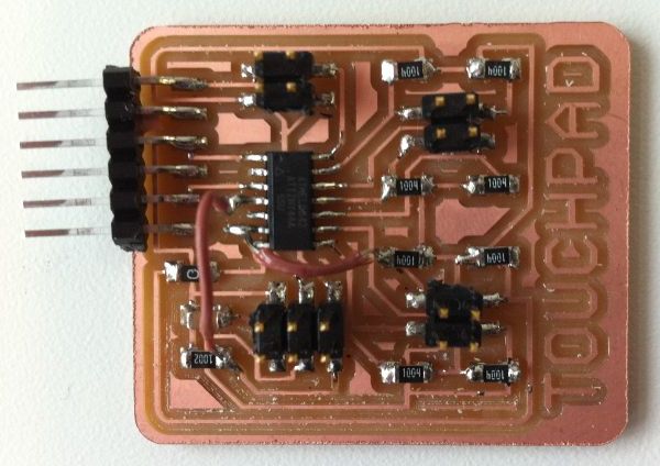
Milling and stuffing the board went off without a hitch. It's getting easier!
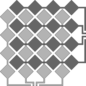
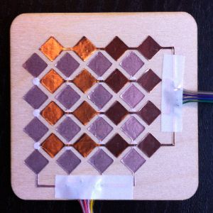
Touchpad design
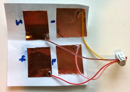
With 8 inputs I figured I could use 4 columns and 4 rows of copper pads to get 16 points of resolution. After playing with several designs (and at Neil's recommendation), I settled on the design below which actually allows for 31 points of resolution through detection of more than 2 rows and/or columns. I cut the design on the vinyl cutter and fixed it to a piece of birch plywood then soldered on cables and a couple of 2x4 pin headers to connect to the circuit board.
Programming the micro-controller
After starting with Neil's step response code, deciphering the data sheet, and a couple of helpful pointers from David Carr, I worked out how to change the analog multiplexer input port and read voltage using step response. I found the 1us voltage reading to vary the most when touching a copper pad so I used a touch down threshold voltage of 700 and a touch up threshold voltage of 750 (on a scale of 0-1023, the output from the A/D converter). Because the 1us reading was deterministic in determining a touch I discarded the 10us and 100us readings. I also found that sending the voltages over serial for every step response cycle was much slower (due to the 10ms delay on each character send being much greater than cycle time) than checking voltages against the threshold on-chip and then sending touch down/up events over serial.
Visualizing the output
Similar to last week, I used NodeJS to read output from the serial port which is sent to the browser using a WebSocket and visualized using ProcessingJS. My visualization shows the location of a persons finger as it moves across the touchpad. To make the movement more smooth (due to the low resolution) I chose to animate between touch points. All code for visualization is provided below.
Files
Touchpad schematic (Eagle)
Touchpad board design (Eagle)
Touchpad design (SVG)
Micro controller and visualization code (ZIP)