Output Devices
Assignment: add an output device to a microcontroller board and program it to do something
For this assignment, I learned
- a)how to add a sensor
- b)how to program microcontrollers
[Output devices]
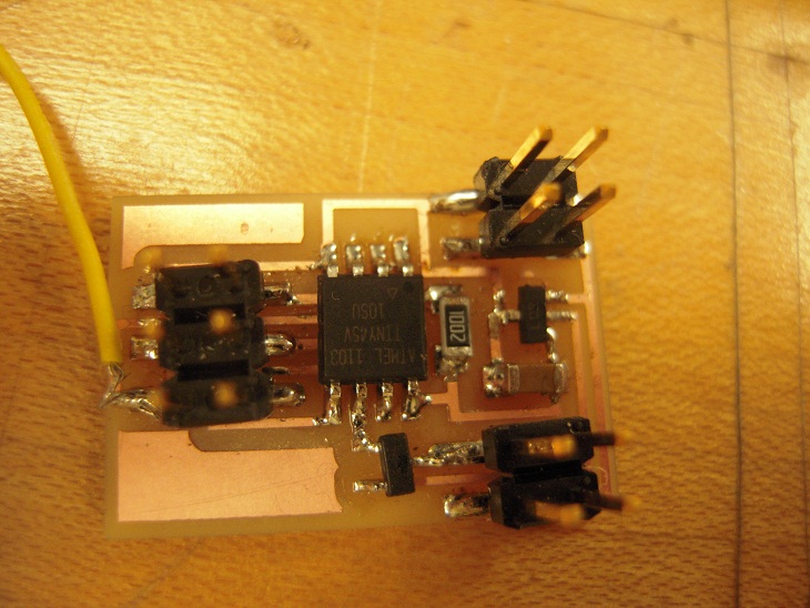
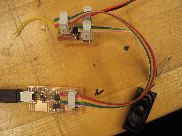
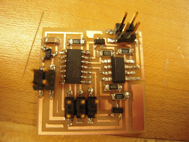
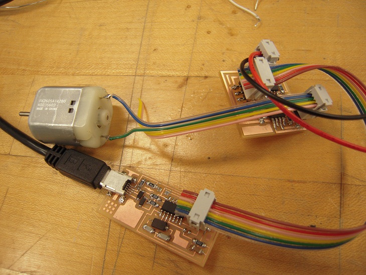
I decided to test a speaker and a DC motor.
Milling board and stuffing went well.
When I programed Neils' codes for both boards, I got rc=-1 and sometimes
avr-objcopy -j .text -O ihex hello.speaker.45.out hello.speaker.45.c.hex;\
   avr-size --mcu=attiny45 --format=avr hello.speaker.45.out
AVR Memory Usage
----------------
Device: attiny45

Program:     262 bytes (6.4% Full)
(.text + .data + .bootloader)

Data:          2 bytes (0.8% Full)
(.data + .bss + .noinit)


avrdude -p t45 -P usb -c usbtiny -U flash:w:hello.speaker.45.c.hex

avrdude: AVR device initialized and ready to accept instructions

Reading | ################################################## | 100% 0.03s

avrdude: Device signature = 0x000000
avrdude: Yikes!  Invalid device signature.
         Double check connections and try again, or use -F to override
         this check.


avrdude done.  Thank you.

make: *** [program-usbtiny] Error 1
I spent several hours with debuging the boards.
It seemed that boards had shorts somewhere.
Connecting with voltage source showed 1V only even though trying to apply 9V.
I repeatedly checked the board, but could not find the physical shorts.(Thanks, Ozz)

For the speaker board, I ripped volatage resulators off and soldered again.
For the DC motor board, the orientation of H-bridge was opposite.
Finally, both boards worked well.
[Fabduino]
Since last week, I tried to make a fabduino board.
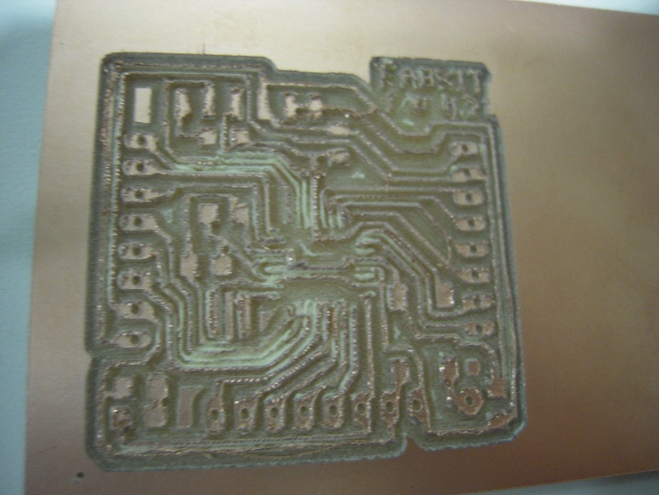
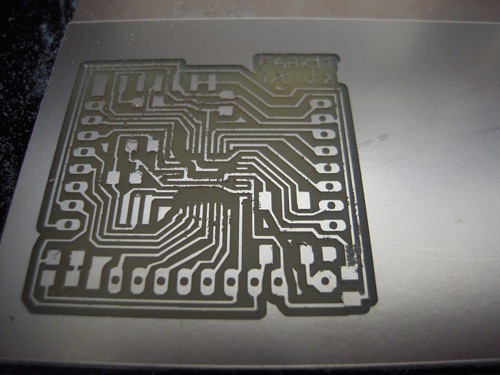
I milled several times (failed to mill holes, the base was moved...) and
finally I got a well-milled board.
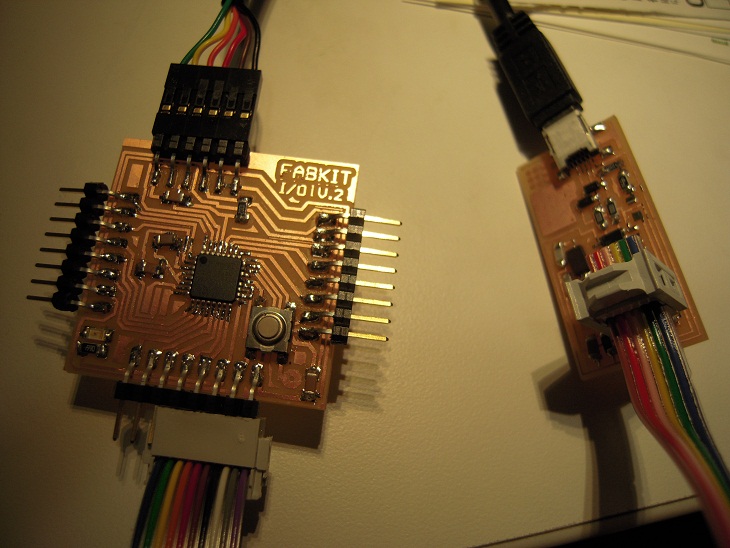
Stuffing relatively went well, but Bootloading didn't, showing rc=-1.
I spent hours for debugging and it worked.
Problem was bad soldering on ATmega168.
 Next, programming.
At the beginning, I thought we have to use pin# of ATmega 168
in Arduino, but it did not work at all. It did not show any
serial streaming.
Got advice from Tiffany, I learned I have to use pin# on the Fabduino schematic
for analog and digital pins and don't have to specify pin# for serial Rx and Tx.
Next, programming.
At the beginning, I thought we have to use pin# of ATmega 168
in Arduino, but it did not work at all. It did not show any
serial streaming.
Got advice from Tiffany, I learned I have to use pin# on the Fabduino schematic
for analog and digital pins and don't have to specify pin# for serial Rx and Tx.
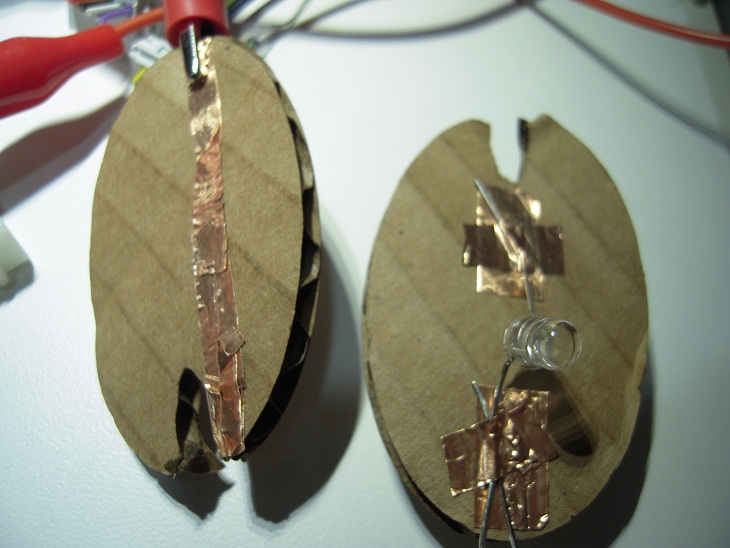
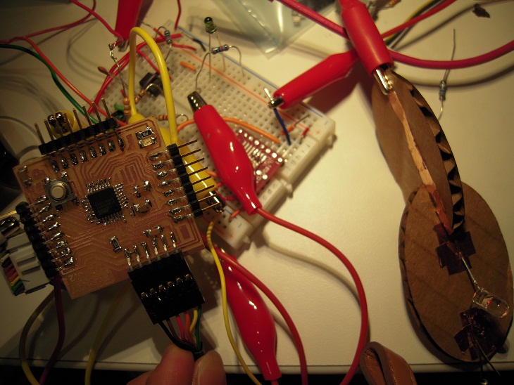
 For my final project, I decided to do a rapid prototype of "press fit circuit".
My idea is making electric connections with press fit construction.
For my final project, I decided to do a rapid prototype of "press fit circuit".
My idea is making electric connections with press fit construction.
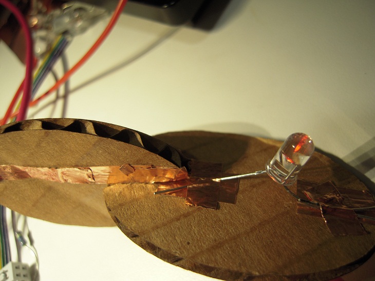
 First, I used a LED and two combined pieces of press fit can make LED light.
Next, tried a LED and a photo transistor.
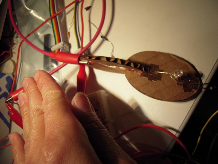
I read the input of photo transistor and output LED depending light intensity.
Covering the photo transistor with my hand makes LED off.
First, I used a LED and two combined pieces of press fit can make LED light.
Next, tried a LED and a photo transistor.
I read the input of photo transistor and output LED depending light intensity.
Covering the photo transistor with my hand makes LED off.
 Now I am trying to read values from a color sensor.