Assignment 1: Cutting Stuff.....
Overview:
Initially, I had high hopes of playing with geometries,
shapes and forms. As the week went on, the focus shifted to
evaluating tools and trying to get the tools to work.
As I started cutting materials, I also started experimenting with the
materials themselves.
The final "product" is a lighting construction set, with a
walk through making motor mounts, and grids.
Experiment 1: Learning CAD, Experimenting with Cardboard and
Mounting Motors
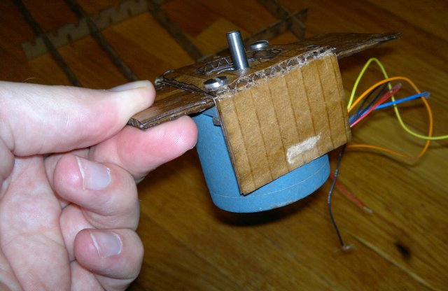
Several of the 3D CAD packages had tutorials for
making plates with holes in them. I decided to make a
plate that I could mount a NEMA23 stepper motor to, out of
cardboard. Surprisingly, the center hole came out a
perfect fit to the face of the motor.
I was wondering if cardboard could be used as a low
cost material that could be used as a partial replacement for plywood
or plastic. Cardboard isn't strong enough to support
several pounds of motor, so I thought I would experiment with using
"Minwax wood hardener". This material costs about
$11/quart, and I used a couple of tablespoons for several cats on the
entire assembly.
This made the cardboard stronger, and looks pretty strong
the length of the ribs, but would buckle if I tried to bend it across
the ribs. Layering two pieces perpendicular to each
other may help. The assembly is weak near the
edges/corner. A better quality cardboard might also
help, or some better "wood hardener".
Conclusion:
- Wood hardener makes the cardboard stronger, and more robust.
- Two layers of cardboard with the ribs perpendicular will make a
stronger assembly.
- The corners and edges are not strong and will still crush.
Experiment 2: Press-fit Pieces
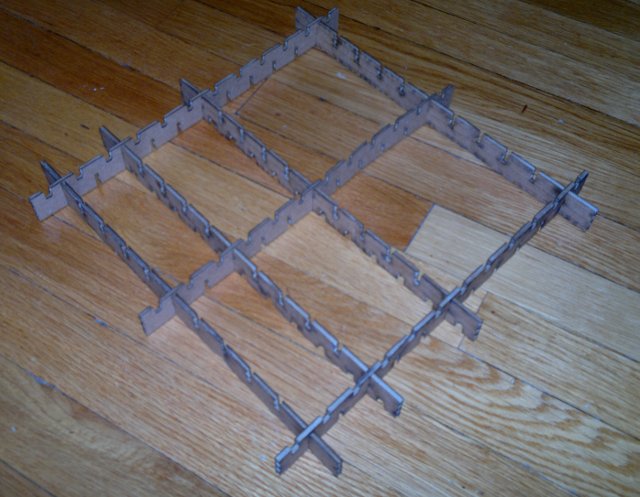
Next I tried to make cardboard pieces that would fit
together in a grid, with an eye towards extending to more complex
surfaces. (With the hope that it could be used
to make a construction kit that would allow making structures/surfaces
for prototype furniture.) This was successful, although the
laser-cutter would make multiple passes over the lines several times.
Setup and cutting time was long, so I only made a handful of
pieces.
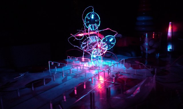
Experiment 3: Lighting Construction Kit
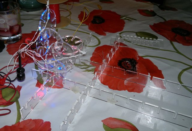
The press-fit pieces made me wonder if they could be used
as a multi-segment light-pipe. I resized the strips for
acrylic, and made a circle with slots that could be assembled at
angles. I cut holes to embed an LED in the pieces.
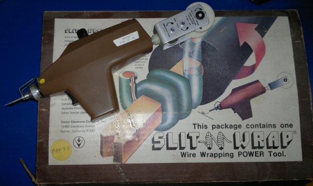
To not violate the "no adhesive rule" of the assignment, I
used a "Star Trek Captain Kirk would be proud" slit and wrap wire wrap gun.
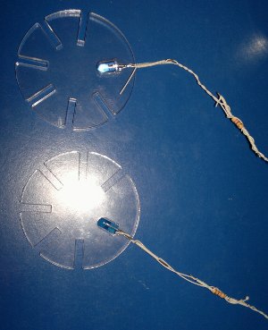
When used with proper wire-wrap pins it creates a MIL-Spec gas tight
joint that is very reliable. I had problems with
the LED pins being too round (the wire-wrap pins are usually square)
and too thin, so I crushed them slightly with a pair of pliers.
The LEDs are powered off a USB battery, and a 330 ohm
resistor is in series with the positive lead of each
LED. (Looking at the LED, the smaller internal part
is the positive.)
Results/Lessons Learned:
- Acrylic isn't the best choice for press fit pieces.
Too tight, and it cracks, too loose, and it does not stay.
Try it too many times, and it scratches.
- Sheet acrylic varies from piece to piece and end to end in
thickness.
- CAD -- Parts seem to deteriorate when I cut and pasted
them. Details seem to get dropped from generation to
generation. This could be my lack of cad
skills. There may even be variances from cut to cut.
The Final Result:
Future Ideas:
- Add more shapes
- Figure out better acrylic/led mounting.
- Think about adding contacts to slots, so that the thing wires
itself.
Implementation notes:
The majority of the files ended up being drawn on
Inventor, and exported to Autocad. This resulted in
3D models in Autocad, and the laser cutter would cut the lines multiple
times. This may have made for wider kerfs, and made
plotting very slow.
Notes on using the Epilog 60 laser cutter.
The kerf through acrylic is .159-.138 = .01 inches
per cut (2 for a slot.. i.e. .02 inches)
For cardboard it is .172-.133 = .019 inches
per cut (2 for slot, i.e. .039")
This may be with the multipass bug in my cad
files... Not sure.
Using Inventor, and chamfer of .03 on openings of
slots for cardboard.
So for .125" plastic we will try .108ish slots,
which are too narrow for the power settings I used. In the
end, I ended up setting the slots to .125"
Copper foil with backing .006" (for conductors
later).