AVR Programmer... Building...

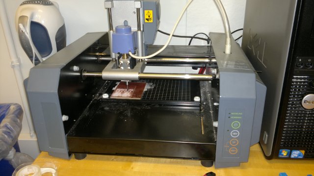
Taking the reference design from the class
page (directions are at the bottom), and the wisdom of my
classmates, the routing of the board was straight forward, with a
slight adjustment of cutter depth. I washed the board with a
scrubber pad I found near the sink. The board seemed a little
rough-- it seemed like the cutter tore the copper more than cut it.
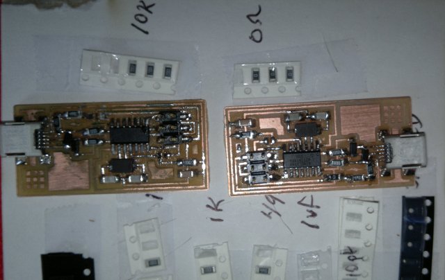
In stuffing, there were some shorts on the USB and programming
connectors. A meter looking for +5V on the 1uF capacitor showed
the board wasn't getting power. The USB connector cleaned
up with some careful solder wicking.
In programming under Linux/Ubuntu I followed the directions.
The software seemed to allow setting of the fuses on the
first run, and then complained that it couldn't talk to the target.
After checking for bridges, resoldering stuff, I built up
the second board, and had the same problem.
Finally, I pulled off the pin header to double check for bridges.
No solder bridges were visible (either looking while looking
under the connector, or once it was pulled. I took a knife, and
carved between the pads to remove any little strips of copper that may
have been left. When I resoldered the connector, it
worked.

Little bits of wisdom gathered....
- The "Z" value (cutter depth) on the fab module needed to be set
deeper -- from the .1 or .2 recommended to .4
- The cuts of the board seemed a little rough. Maybe
sanding the board a little would have helped.
- Check for +5 volts when testing. If it isn't there,
then there is a short.
- A quick scrape between the pins with a knife might have helped
with shorts.
- The flux pen made it easier to solder.
Other minor discoveries/projects...
- Played with Eagle, ordered parts for motor
controllers.
- Inkscape will generate gears! Need to
try out on the laser cutter.

