Assignment 7 -- Input Devices -- Drawing A Box!
(Or, my attempts at building a laser scanner, )
Introduction:
This week, I thought it would be fun to try to
implement an idea I had for a laser scanner, using some parts I picked
up here an there. Neil's lecture extolled the virtues
of the tiny45, so I got geeked about that. I was less
geeked about ordering a FDTI cable, so I thought I would look at using
software USB support. How hard could it be?
The board and reference design:
I did a quick scan of USB on the tiny45 and analog
I/O. I came across this project for a 5
pound oscilloscope. Looked like a good place to
start. I relaid out the board to use surface mount
components, and to incorporate the connector. The
board can be seen here:
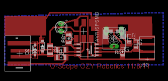
Too bad it is all about windows software. I
thought, I'll just rewrite it! How hard can it be to
get some USB drivers running. How long could it
take? (Ans: 4 days, ugh...)
USB on a little processor that wasn't meant to run it:
Has multiple modes and endpoints. The
protocol tends to be complex. You typically need
software on both ends of the link to make it work.
The USB code I used is based on the V-USB project.
I looked at:
- HID devices --
which are normally for keyboards and mice. Initial
survey suggests that packets are about 8 bytes. While
I looked around for quite a while, the code I finally used was a
combination of the oscilloscope code, and here.
(Of course, the good tutorial I find after a few days of pain, and a
couple of stupid bugs that led me down blink alleys) On the
Linux side, I adopted his libhid example.
- Communications device --
(driverless on the host -- looks like a serial port.) This
code was based off of some sample code here. This code worked
somewhat, but I had another bug that was causing problems.
Notes:
- I had a bug addressing the I/O port and was trying to use one of
the USB pins as an ADC pin. The driver would disappear.
- The host side (Linux) side would appear to lock up after 13-60
messages. The tiny45 was using the internal RC clock
(no crystal like used in the demo code.) I added the
clock cal routine from the oscilloscope code, and that improved
reliability, but I can't be fully sure that there weren't
communications errors.
The Scanner:
Overview:
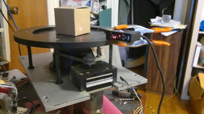
A small industrial laser scanner
sits to the side of a rotary table. The object is placed
in the middle of the table. With each read command from
the host PC, the tiny45 reads the laser range information, and
increments the motor -- placing the packets on a usb port.
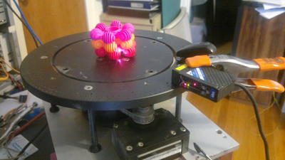
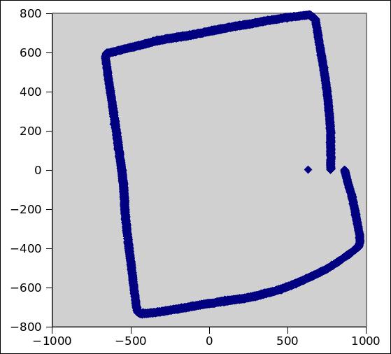
After about 16000 readings, the perimeter of the object is
digitized (hopefully). The host PC then translated the polar
coordinate data to X-Y coordinate data.
measuring
Was built out of a flea-market industrial laser scanner
for measureinike bottle caps being mis-seated, or too thick of paper
going into a printing press. It appears to shoot a
HeNe spot on the object and has an active range of about 2-6
inches. The output I used was a 4-20mA current loop
output, which I hung a 240 ohm resistor across and hooked to the ADC
pins. The maximum observed output was about 300-2500
counts on the ADC, when the target is out of range the reading
drops to below 200.
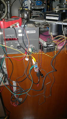
The rotary table is out of a piece of semiconductor test
equipment, and is driven by a stepper motor. The
motor is driven by an Intelligent Motion Systems IB463 stepper
driver. The tiny45 toggles the step_clock input and the motor
moves one step. With the gearbox and belt, the table
has quite a bit of power, and operates smoothly.
About 16000 steps appear to make a revolution.
Results:
Since nothing was calibrated, I think it is quite
impressive that the plot basically has four sides. Knowing
the number of steps per revolution, and knowing how the sensor output
corresponds to the physical range would probably improve the output.
Other:
- The magic 8-ball from last week broke loose with the help of a
screwdriver. Works now, but doesn't shake well.
- the Mega168 board from two weeks ago is fixed
- Made a simple tiny45 board. Need to respin to have
right pitch headers.