Assignment 8: Output Devices
This week, I knew I wanted to do some motor control -- a
necessary component of my future thoughts of making modular
machines. Steppers work open loop, and in the design
stages of the week, I was looking at controller chips, creating Eagle
footprints, and experimenting with laying out some
boards. Many devices are now in a HSSOP package, and
it looks like boards should be rapid-prototypable.
Some things came up, and my implementation/debug/test time
was short this week, so I scaled back to stuffing what should be the
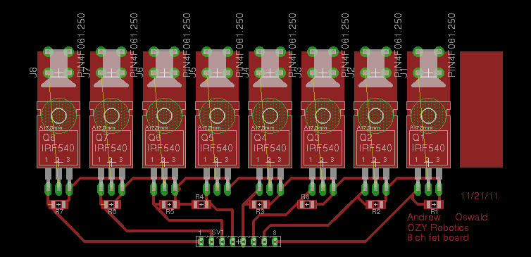
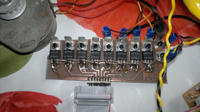
simplest board... an 8 channel MOSFET board using a bunch of
IRF640's. I then attached a unipolar (six wire
stepper).

After layout and etch, I tacked some diodes on, since the
loads would be inductive. The interface was designed
to work with my board from assignment
5.

I had high hopes for USB and a couple of steppers without
a controller. Unfortunately, I would be short pins,
and time. Maybe next week?
How to debug?
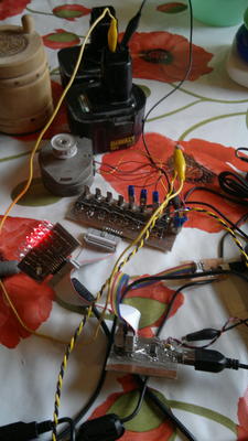
What was cool, was that I could add a connector to the
ribbon cable, and then plug in my blinkey light board also from the
assignment 5 week. This meant I could watch the bits
twiddle as stuff ran! Great fun, and a big
help. Here is the assembled layout.

Results:
Lights blink! Motor Spins! Torque
sucks. I suspect that I may not be driving the
mosfets hard enough to turn them on for higher
currents. I should also double check my drive
algorithm. It will be a handy board, but it might
need to go to a second rev.
Notes:,
Compressing video:
ffmpeg -i
11212011040.mp4 -ar 22050 -ab 32 -f flv -s 400x300 video.flv
Is the A3977 and the DRV8811 pin for pin compatible?


