For this assignment I wanted to set up for an experiment involving touching object without seeing them. The definition of a brain-box experiment is exactly what I was looking for: The objective is to put something into the box and then have other people try to guess what it is just by feeling/touching it with their hands. The project involves the construction of a box in MDF or Foam using the Shopbot CNC. I also developed my initial idea from Project 1 by building the 'Finger Extensions' in aluminum using the Waterjet cuter. I run into a lot of problems with the CNC though. These problems are detailed below. The Waterjet worked out fine.
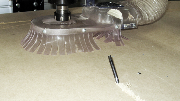
PROBLEM 1: I started trying to build the box in MDF (0.75" thick). In the first attempt I broke the bit (0.25"). I don't know what the problem was. I used 3 passes to mill (0.25" each) and a speed of 100 inch/min.
PROBLEM 2: The Shopbot is located in the basement of building 10 and it is isolated from other shops. Therefore we are alone down there without supervision and there are no other tools to use. This is a problem if you want to do other complementary processes. I had to move the MDF from the Shopbot to the Woodshop in N51.
PROBLEM 3: I started milling the 3D surface of the box. This time the bit didn’t break but it changed Z height during the process! I don't know how/why this happened. I fastened the screw tight enough before starting.
PROBLEM 4: I used Partworks 3D to mill the 3D model. Partworks 3D is easy to use and it guides you through the steps clearly. However, everything is predefined for you and you can't customize the settings. I run into a problem because the program creates contours equally separated (I tried 0.4" and 0.5") and therefore some of the geometry doesn't fit or match the contours. I only found that out after milling my part. The contours are good for general 3D surfaces in which you don't care much of the details. I fixed this problem by generating two different files: one for the surface in Partworks 3D and one for the pockets and profile in Partworks 2D. I had to be careful in keeping the 0 (x,y,z) coordinates.
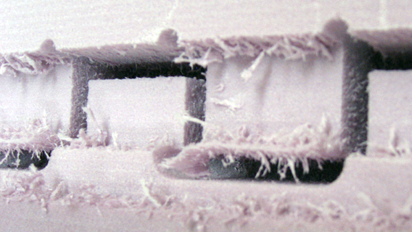
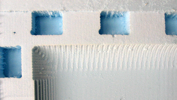
PROBLEM 5: Everything supposed to work perfect... but: The finishing of the pockets and profile was not smooth. This didn't make sense to me at first but then I remembered the climbing vs conventional way of moving the bit. I checked that and realized that the default were climbing. I change to conventional which worked out fine.
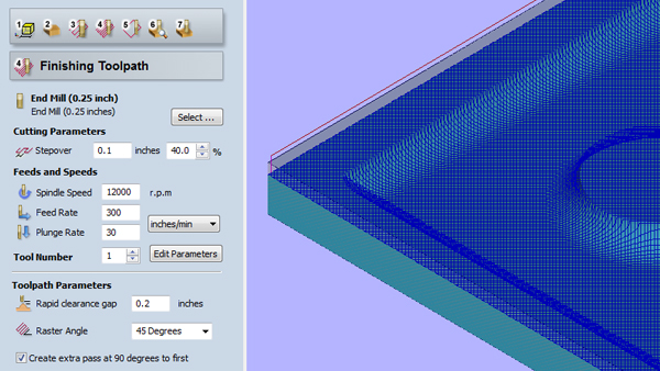
This image shows the parameters I used in Partworks 3D. Step Over: 40% (Didn’t have time for more resolution). Feed rate: 300 inches/min. (which is very fast, possible only in soft materials such as Foam). There was an important difference in the estimate of time. Partworks calculated 28 min. which turned out to be more than an hour in reality.
The simulation of the 3D surfaces is actually pretty good in Partworks. I found very helpful to be able to decide parameters according to these simulations.
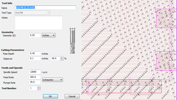
This image shows the parameters I used in Partworks 2D. I used the same settings I used for surfacing and it worked out fine. Step Over: 40%. Feed rate: 300 inches/min. I used 3 types of pockets (the part's heights) and 2 types of pockets (inside and outside). Here are the Shopbot Instructions (thanks to Craig Boney)
Shopbot Instructions
[A]
01. Partworks 3.0 for fixed plunge milling, Partworks 3D for contour milling.
02. Change bit, properly seat.
03. Put key back in (barely turn to the right...like 45 degrees).
[B]
01. Open Partworks.
02. Create new file.
03. Create fillets tab...follow the directions.
04. Set profile path (this writes the gcode)...toolpath.
- Create profile toolpath.
- Add .05" to total depth of material.
- Set plunge depth = .125 typ for 1/4" bit.
- Calculate (warning tab no problem).
05. Save toolpath.
06. Get profiles in order.
07. Save toolpaths.
08. Save as .spb file.
09. Open in shopbot program.
[C]
01. Turn on blue reset for first time.
02. Yellow buttons on screen.
- Move machine around until you find 0,0.
- Center material to router.
- Zero x + y.
03. Zero Z.
- Set tuning plate.
- Clip alligator to bit.
- Hit zero button.
04. Load part file.
05. Turn on dust collector.
06. Turn start on machine first.
07. Run part.
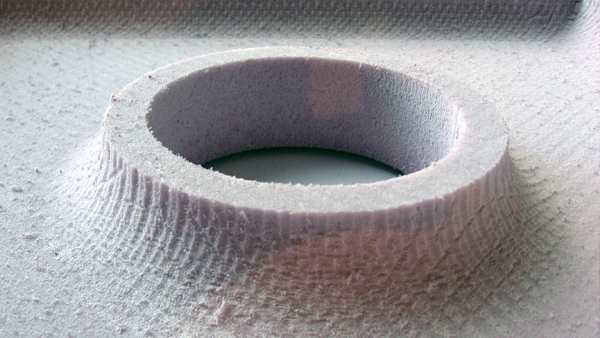
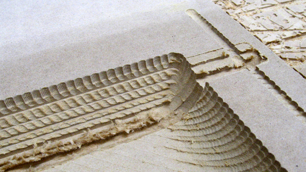
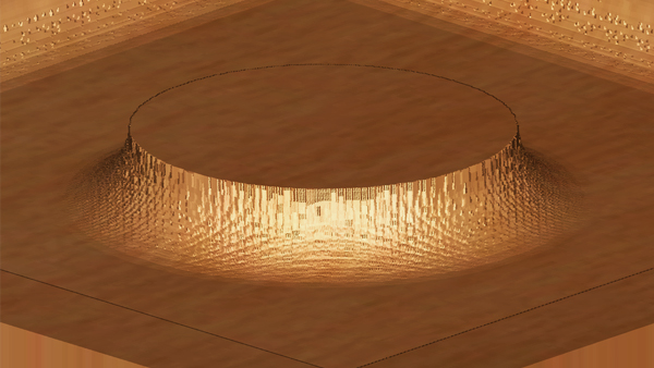
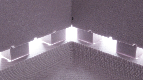
This image shows the final surface finishing which was very close to the Partworks simulation.
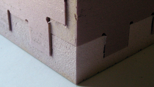
The result of combining Partworks 3D (for surfacing) and Partworks 2D (for pocketing and profiling) was satisfactory. The only difficulty was using two programs to generate two .shp files and keeping origin point the same in both.
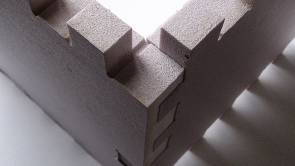
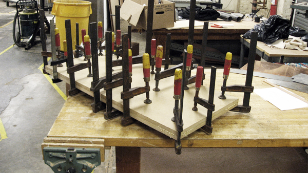
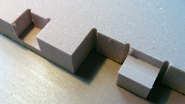
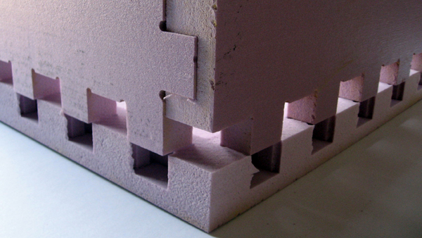
The assembly process worked out fine. The Foam contracts enabling a perfect fit between components. One problem though was the thickness of the material. I measure 1.95" inches which was not even throughout the Foam.
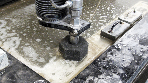
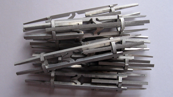
I used the Waterjet to cut the 'Finger Extensions' from Project 1 in Aluminum.
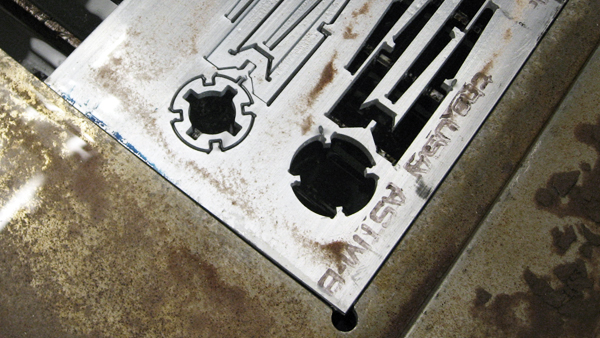
The parts are very tinny and therefore I had to include tabs to support them.
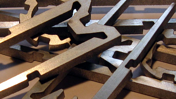
The result was very satisfying and much better than the previous version using Plexiglas and the Laser cuter. I reduced the width of the parts from 1" (Plexiglas) to 0.75" (Aluminum). The components are more robust in aluminum too and the assembly process simpler and reversible.
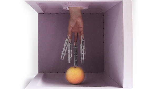
The experiment is now ready to be tested: The 'Brain-box' + the 'Finger Extensions.' This experiment will help understanding what it feels to touch different objects with extensions or sticks without seeing. The idea is to then use the result to guide and evaluate the Final Project which will use infrared sensing and haptic feedback without actual physical finger extensions.