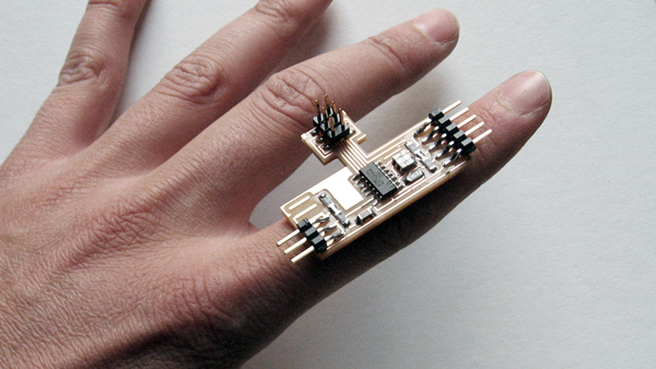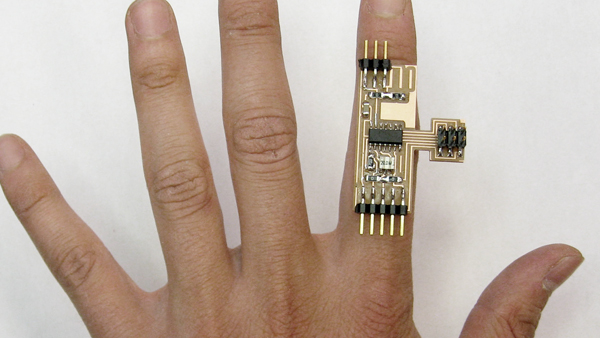
For this assignment we had to design a microcontroller board to be programmed through the FabISP made in assignment 2. I tried to design a board with the smaller width as possible, so that I could attach it to a finger for my final project.
Before Getting Started it is important to install some programs and drivers, and download some files.
[A] To design the circuit board:
Install Eagle and download the Fab Library.
[B] To recognize the programmers in Windows 7 (in Mac this is not necessary):
Install the USBTinyISPdriver (if using FabISP) or the AVRISP driver (if using the AVR programmer).
[C] To program the Atinny44:
It is possible now to use the Arduino environment to program the Atinny44. You need to download Arduino 1.0 and follow Devid Mellis’ tutorial. Another alternative is to program in C. For that you can use AVR Studio or simply use WinAVR through your computer’s terminal or Cygwin.
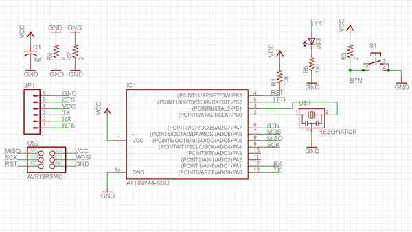
Schematic design in Eagle of Atinny44 with a push button and LED.
Eagle Instructions (Basic Commands)
[A] Schematic Design
NET: To trace connections in schematic.
NAME: To name components and traces.
LABEL: To display the names.
ADD: To add components from Library.
ERC: Electronics Rules Check.
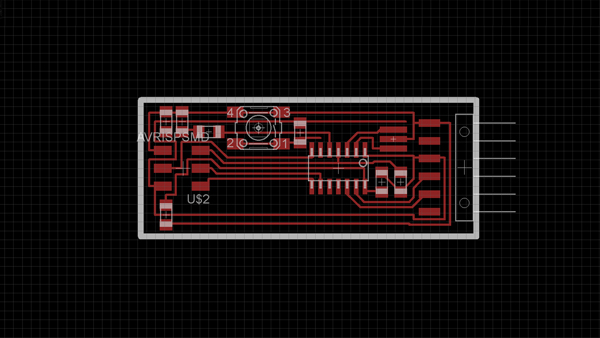
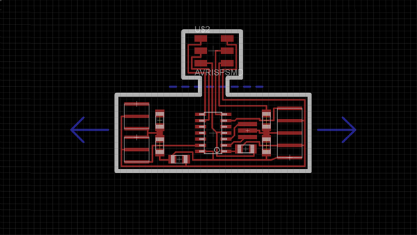
Board design in Eagle of Atinny44 with a push button and LED.
Eagle Instructions (Basic Commands)
[B] Board Design
GRID: Define resolution for traces design.
ROUTE: To trace connections in board (use 0.012).
WIRE: To draw board profile (use 0.032).
RATS: To check connections.
RIPOUT: To delete traces.
GROUP: Right click to move or rotate selection as group.
DRC: Design Rules Check.
To export the png. for fabrication turn on the layers you need (Top and Dimension). File => Export => Image. Use monochrome 2000 dpi.
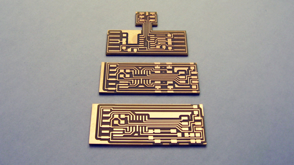
FaBread 1: I designed a circuit to be used as a 'bread board' with Vcc and GND lines in both sides. The idea is to modify the board for the requirements of a particular design. A good way to 'stretch' the board is to select the section you need, then right click and "move group" command.
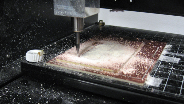
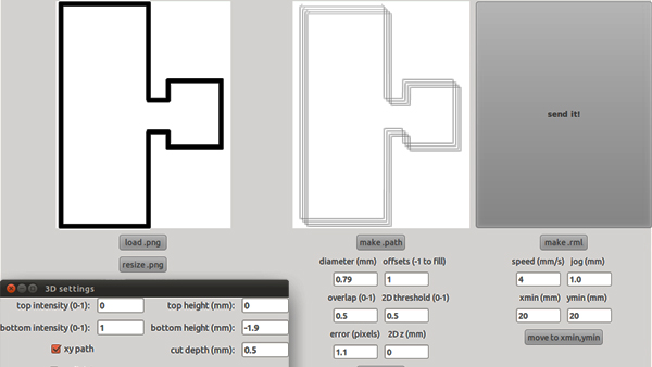
As in assignment 2, we used the Roland Modela milling machine and the
Fab Modules to score and cut the PCB board. We used a 1/64 bit to score the circuit and 1/32 bit to cut the outside of the board.
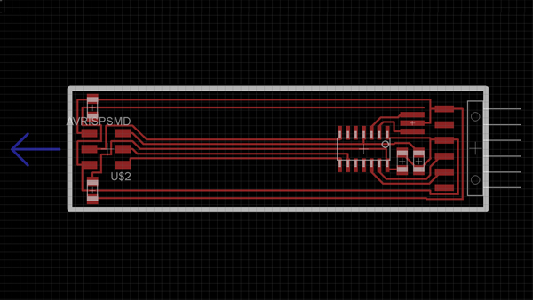
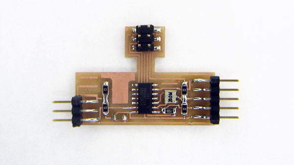
FaBread 2: This design has less width than FaBread 1 and can grow in both directions. The original design uses an FTDI cable for serial communication. I decided my project doesn't need communication with the computer and therefore the board layout could become simpler. Also, the connection for IDC ISP cable can be cut after the board is programmed.
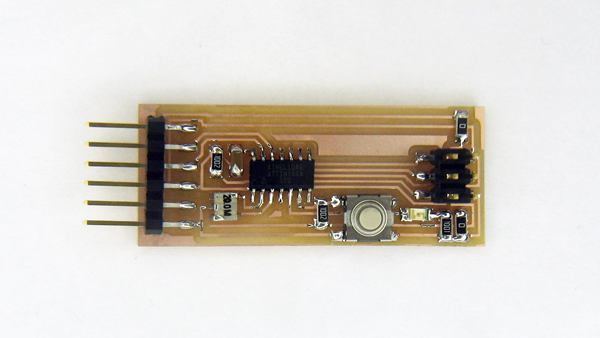
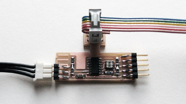
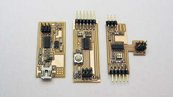
Final boards after milling and soldering: FaBread 1 (above) and FaBread 2 (below).
Programming Instructions (using C)
[A]
Download the hello.ftdi.44.echo.c and hello.ftdi.44.echo.c.make files. Keep the files extensions (.c and .make).
[B]
Edit the files in Wordpad or AVR Studio. Follow the microcontroller datasheet
and David Mellis’ AVR programming tutorial or Ladyada's AVR tutorial.
[C]
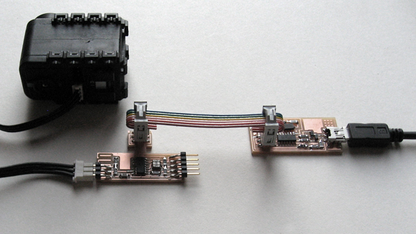
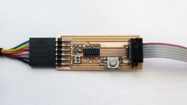
Connect your Computer, the FabISP programmer and your Atinny44 board as shown in the image below.
[D]
Open the Terminal or Cygwin and type:
make -f hello.ftdi.44.echo.c.make (build the .hex file).
make -f hello.ftdi.44.echo.c.make program-usbtiny-fuses (fuse bits on the chip)
make -f hello.ftdi.44.echo.c.make program-usbtiny (program with hex file)