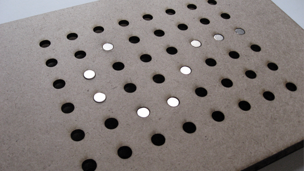
I really liked working with electromagnets so I decided to change my final project. Instead of giving haptic feedback through a glove (which turned out to be very hard), I will use a pad with an array of electromagnets. I call this project the haptic-pad.

I found a very nice reference called the Actuated Workbench. It is mainly the same system, an array of 8 by 8 controlled electromagnets. The haptic-pad is not about moving objects or interfacing with the computer though, but rather is about giving feedback to hand movement, as in the original final project the haptic-glove.
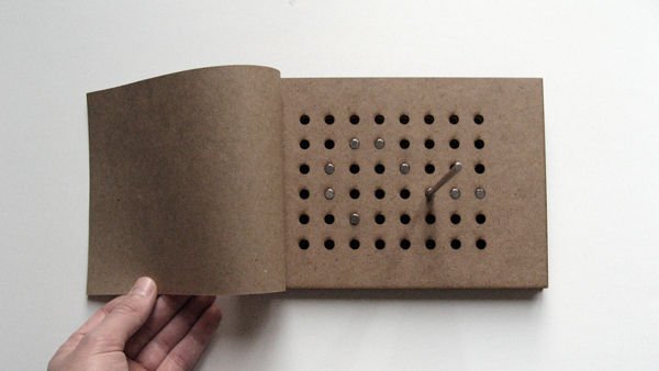
The idea here is to display 3D 'images' that could be 'touched" by the hand or through a pen with a magnetic head. I imagine this system used as a sort of paper-based drafting tool with invisible snaps and rulers (like autocad using regular pen and paper).
I wanted to use Charlieplexing to control the array of electromagnets. I didn't work though, because I need to use mosfets (to provide enough current) and therefore I canont use the 3 state capabilities of the pins (Attinny cannot sourse-sink enough current).
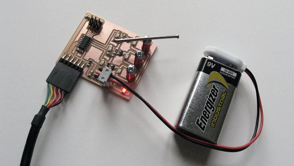
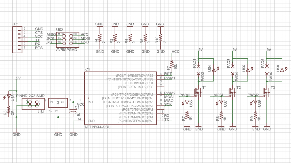
I decided to start simple and control 3 electromagnets through 3 pins (PWM) and a simple interface (in Processing). I found some hardware problems though: I burned the voltage regulator. I think I need a diode between the regulator's ground and the ground of the mosfets' loop.
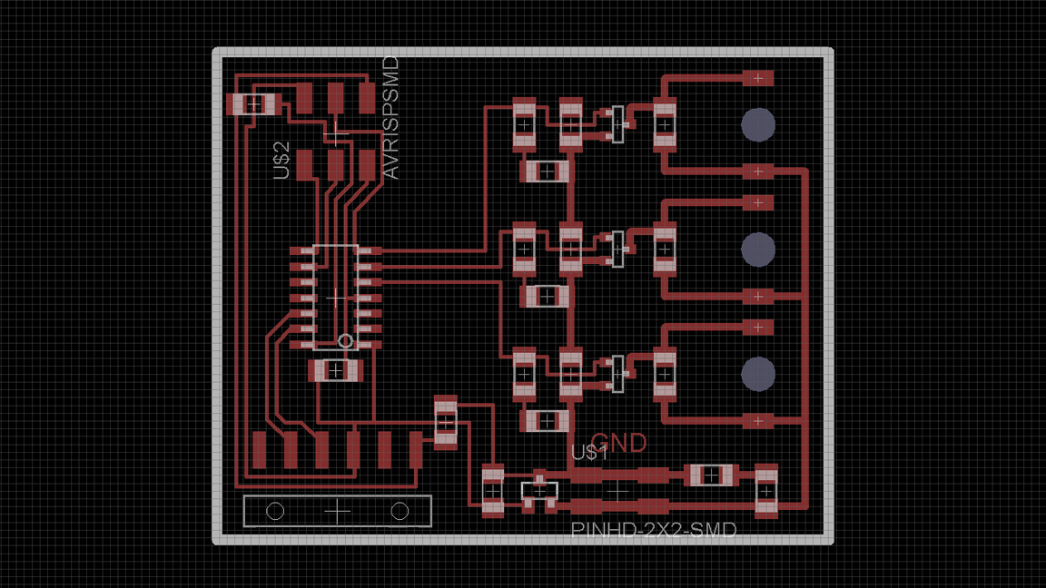
Eagle files (Schematic and Board Layout).
Code files (Arduino and Processing).
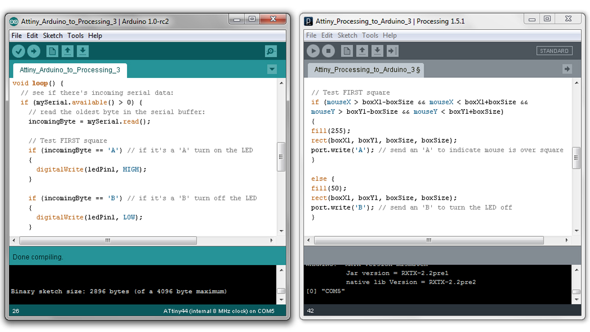
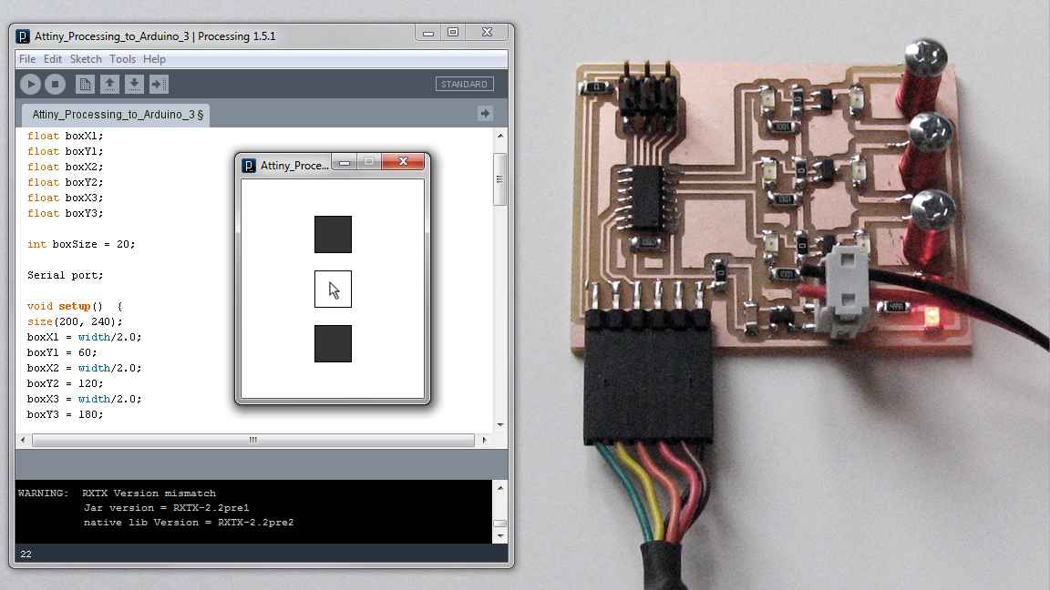
The Arduino-Processing interface and communication worked out pretty well. I just modified David Mellis' Physical Pixel project. I included 3 squares, one for each electromagnet: if the cursor is over a square, a specific byte (ASCII character) is transmited to the board through software serial communication.
A byte corresponds to eight bits, character 'A' = 1000001. I used characters from A to F. For example, if the cursor is over the second square a 'C' (1000011) is trasmitted to the Attinny, which turns pin 7 (PA7) HIGH (5V) activating the corresponding n-mosfet and therefore turning on the electromagnet.
ARDUINO (key code lines)
SoftwareSerial mySerial(0, 1); // (rx,tx) of the microcontroller
int incomingByte; // a variable to read incoming serial data into

void setup() {

  mySerial.begin(9600); // set the data rate (same as Processing)
  pinMode(6, OUTPUT); // initialize pin as an output
}

void loop() {

  if (mySerial.available() > 0) {

   incomingByte = mySerial.read(); // read the oldest byte in the serial buffer

   // Test FIRST square

   if (incomingByte == 'A')
   {
    digitalWrite(6, HIGH); // if byte is 'A' turn pin 6 HIGH
   }

   if (incomingByte == 'B')
   {
    digitalWrite(6, LOW); // if byte is 'B' turn pin 6 LOW
   }
  }
}
PROCESSING (key code lines)
import processing.serial.*;
Serial port;

void setup()  {

  println(Serial.list()); // prints ports
  port = new Serial(this, Serial.list()[0], 9600); // set the data rate
}

 void draw() {

  // Test FIRST square

   if (mouseX > boxX1-boxSize && mouseX < boxX1+boxSize &&
       mouseY > boxY1-boxSize && mouseY < boxY1+boxSize)
   {
    port.write('A'); // send 'A' to port (mouse is over square)
   }

   else
   {
    port.write('B'); // send 'B' to port (mouse is not over square)
   }
}