We're now counting down towards the end, and I have begun work on my final project! This page will serve as my design log, and I will be updating it regularly with small additions as I (hopefully) continue to make progress towards completion! First, I'll introduce the plan and the timeline, and then further updates will be made as time goes on.
Final Project Plan
My goal is to design a small electric generator that can generate electricity by shaking it (think of a shakelight flashlight), and then design a small LED array that can be powered by this generator. I want the generator to be small and portable, so that it can be fastened to the spokes of a bicycle wheel so that you can generate electricity while you ride. If this design works out and I have time left (ahahaha...) I want to design a different version that fits in your pocket and looks like a dodecahedron. In addition, I want to find a way to do this with the cheapest materials possible so that this could be re-created in places with fewer resources at their disposal.
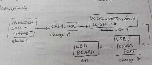
Conceptually I mapped out how my project would work:
The inductor coil and magnet will generate current.
The capacitor will store a charge.
I'll build a small circuit with a microcontroller and switch that can be used to supply power to the LED array.
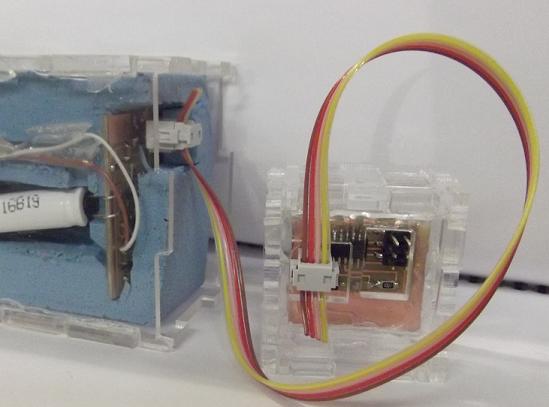
There will be a connecting cable between the LED array and the power source.
The LED board should light up automatically when power is supplied to it.
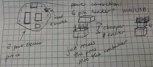
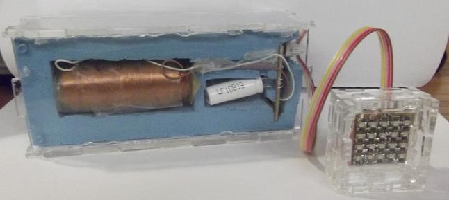
Here's the cylindrical configuration of the power generating part of my project. I think I may use plastic ties to attach the assembly to a bicycle spoke instead of what is drawn there, however. I also plan on using a 6-pin header instead of a USB connection to power my LED array.
I was speculating how I would arrange the pieces in a dodecahedron shape, as well as contemplating various ways of suppling power to the LED array.
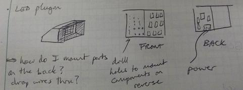
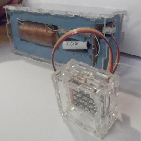
This is how I see my LED array being housed. I want to build the housing out of press-fit acrylic pieces - I'll use a piece of acrylic as an intermediate layer in the two-layer LED board. I also will line the inside of the front of the housing with aluminum foil to make it more reflective so that I get a better light output.
Timeline
I think that I can do this project in the time that I have left, and I've mapped out the milestones I need to hit in order to do this.
Sunday
Monday
Tuesday
Wednesday
Thursday
Friday
Saturday
1
2
3
4 A
5
6
7 B
8
9 C
10
11 D
12
13
14 E
15
16
17 F
18 G
19 !!!
20
21
22
23
24
Milestones:
A: Complete inductor coil
B: Work with TA on electronics
C: Complete electronics
D: Finish design for Oomoo mold
E: Cut Oomoo mold and cast it
F: Complete acrylic frame
G: Debug
A: Working on Inductor Coil
This weekend I got an inductor coil to work in generating voltage. Thanks to Daniel for the advice! Below are some of the things I learned while putting the coil together, as well as a video of the working coil.
Be sure the diameter of the cardstock guide you're using doesn't shrink when you start wrapping the wire; I taped the two ends flush to each other so that they couldn't slide over each other.
Scrape the two ends of the magnetic wire with steel wool or sandpaper before attaching them to the multimeter electrodes.
For that matter, be sure you've got the starting end of the wire taped down somewhere you can access it later when you want to measure voltage.
The inductor coil produces AC, not DC.
Be careful not to break the magnetic wire - its very fragile!
I obtained about 0.3V with the magnets from the shop; with some of Daniel's N52's, I got 0.5 - 0.7V.
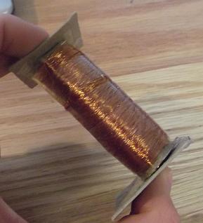
Here's an update on the inductor coil: I was able to wind a much larger version this week using a drill which rotated my spool as I fed magnetic wire onto it. I used cardstock to make the basic spool, and its slightly larger than the diameter of the magnets I'll be using, so they slide up and down quite easily. It should be noted, though, that the magnetic wire is really really fragile! I know I said that before, and I mean it! I broke the wire a couple times and twisted the two ends together. I still obtained 0.5 - 0.7V, and even got over 1V at times, though, so I think this one is a keeper (also it takes a ridiculously long time to coil that much wire, so I'm not interested in doing it again). A picture of it is below:
B: Working on Electronics
I want to thank David Mellis and Dhananjay Gadre and Ranjit Puri for their help on my design of my electronics board this week. I credit Dhananjay Gadre and Ranjit PUri for their board design which I adapted slightly for my own application; you can find their entry in the Atmel AVR Design Competition that I used here. Thanks to David Mellis for sitting down with me and explaining the function of a DC/DC converter to me, as well as other components in my circuit.
As part of the board design process, I also had to build my own part in Eagle for the DC/DC converter I was using (it was a MAX756), and I want to credit this Instructable (thanks Jennifer!) for giving excellent instructions on how to build the part. Below are my Eagle files, as well as the one-part library I created containing the best approximation of a MAX756 I could make:
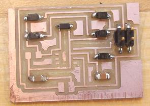
I did complete the board this week, and below is an image of it stuff - I'm still missing a couple of components, however, which should arrive this week at which time I will stuff and debug the board till it works!
The parts I'm still waiting for include:
2x MAX756 DC/DC converters at $5.48 each
5x PCD1425CT-ND (inductor 22uH) at $0.34 each
C: Complete Electronics
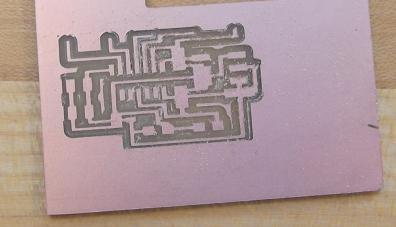
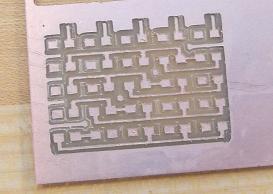
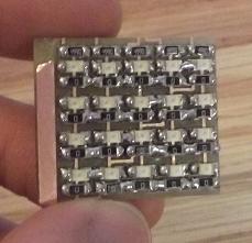
I also fabricated my double-sided LED array this week. At first I tried to remake Prof. Gershenfeld's LED array 2, but when I brought the PNGs I had into the fab modules, they would not recognize the size of the PNG file. I re-saved the files in GIMP editor, then brought them back into the Fab modules and resized them so that they would be close to the correct dimensions (I had my board from the output devices week with me to compare). Unfortunately, I got the sizing off, as you might have guessed, and the traces came out too small. I'm not sure why I had this problem today, but not on Wednesday when I was milling my other board. It may have had something to do with the way I saved my PNG file? Here are some pictures of the messed up boards:
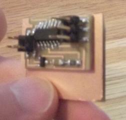
I then went back and cut up the PNG image of Prof. Gershenfeld's LED array 1 and made it in two parts so that I could make the board double sided. That was much more succesful, and I know that the board works because when I tried using some copper vinyl to make temporary connections, I got the LEDs to light up briefly (the connections are poor); later on today I hope to repair the connections using some solder and wire. I also noted that there was some smoke coming out of my board when it was connected to power - I will have to debug that too. Is it necessary to remove the copper backsides on both boards before I glue them together?
Here are some more pictures of my completed LED board:
D: Design for Oomoo Mold
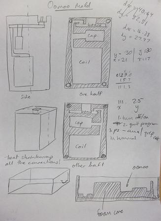
I fell a little bit behind here as I have not yet made the model for my Oomoo mold - I hope to do that before Wednesday, however, as I have already arranged to use the Shopbot with Shahar on Wednesday morning, when I will mill my molds into pink foam core. I did manage to get a quick sketch done of how the mold should look conceptually - that's show below:
This is my final update of the semester! I wish it could end on a happier note,
as I have not been able to complete my final project. I have built all the components
but as of right now my capacitor is not charging and so I cannot power my LED array.
Before going too in depth into the debugging process, however, let me tell you a little
more about this past week's progress and what I built.
Using the Shopbot to make a Mold
My first project this week was to make the foam mold that I would eventually cast
my Oomoo container in. I created a Solidworks model of the negative space of my mold
and then imported it into Partworks 3.0 to make the Shopbot file. The one frustrating
thing about this process was that I wanted cavities with different depths in my mold,
which I included in my Solidworks model, but this did not get translated over to
Partworks 3.0 with the .DWG file I was using. This was just an inconvenience because
I had to reprogram the depths into the file, and each outline for each cavity became
a separate layer in my Partworks file.
Here are my Solidworks and DWG files for the mold I did cut:
I also found that one of the two halves of my mold was too tightly packed for the
Shopbot to be able to mill out with an 1/8" endmill. Regardless, I decided to mill the
one side the Shopbot could do accurately (thanks to Shahar for working with me!) and
then I tried to use the Modela to mill out the foam with a smaller endmill.
Using the Modela was a little challenging because the Fab modules had trouble
converting my STL files to anything other than a single rectangle. I finally figured
out that the outer rectangle of material in my Solidworks model was confusing the Fab
module and so I deleted it and just kept the inner cavities. That worked well and so I
got the Modela running. However, looking at how deep I needed to mill (3.75 cm), and how
big it was (roughly 6 cm by 15 cm), I realized it was going to take a really long time
for the 1/32" endmill to cut my mold, and so I abandoned that half of the mold.
I decided I would use an acryclic case to hold the one half of the mold I did have,
instead.
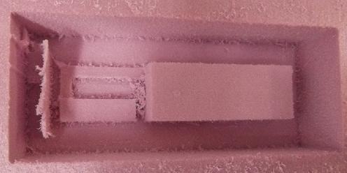
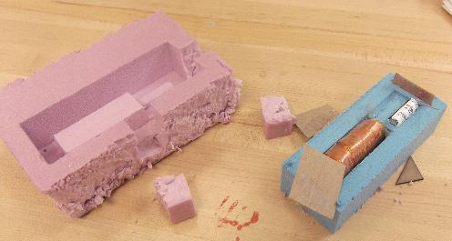
Meanwhile, while figuring this out I also successfully cast an Oomoo part in the
mold I had cut on the Shopbot. I hadn't given any thought to how I was going to get
my Oomoo part out, which resulted in collateral damage to my foam mold during the
extraction process. (See image below for full comprehension of carnage.) Something to
consider next time I make a mold for a hunk of Oomoo...However, my components fit
well, barring the need to increase the height of the cavity for my PCB, because I
hadn't taken into account the height of the components as well as the board itself
when designing the mold.
Laser Cutting the Acrylic Cases
My next step was to design and cut the acrylic cases for both my LED array and the
Oomoo mold. I used Autodesk Inventor because I prefer their Manage Parameters functions
for when I needed to create press-fit connections. This part of the process went
reasonably well; my first iteration had tabs that were too large, and so they didn't
press fit at all. I redesigned and recut them the next day, and everything fit well -
a little too well, actually - I confess to needing glue to hold the parts together,
as the tolerances are now too wide instead of too small. Another oops. With one more
iteration I probably could've come close to perfect, but I also found that the laser
cutter wasn't cutting perfectly right angles, so any smaller and I might not have been
able to fit them together due to that issue...
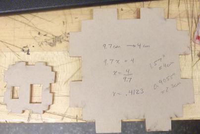
As you can see, the scaling didn't work quite right the first time (the one on the left is the correct size); hence the quick mathematics on the paper backing of my first attempt!
A Quick Word About the LED Array
Making this array was interesting because I made it double sided. I struggled to debug
it because only 2 of my LEDs were malfunctioning, which suggested to me that it wasn't
a power connection issue, but a local problem with the LED components themselves (maybe
I'm wrong about that). At any rate, after replacing the components with fresh ones, I had
the same problem. I also found that my connections across the two sides of the board were
loose, so I reattached them all. This just made things worse, as I now have a 3x4 grid
instead of the 4x5 grid I began with. I have left it this way, however, because for time's
sake I thought powering 12 instead of 20 LEDs would still be an awesome proof of concept,
and heck - that's just a smaller load on the capacitor, anyway, right? Yeah. I meant to do
that.
Redesigning the Inductor Coil Circuit Board
This week Brian was kind enough to offer office hours for electronics debugging,
which I took advantage of because when I first connected everything, I found that nothing
worked. As it turns out:
I didn't route a connection between the SHDN pin and the other side of the Dc/DC
converter chip.
I was missing a couple of other routes between the converter's pins and other
elements on my board.
I had hoped to use a 100uF capacitor, but we had none in the lab, so I put 10
10 uF capacitors in parallel instead.
Brian also suggested that the supercapacitor (10F, remember!) was going to take a
long time to charge, and that I would be able to see it charging by measuring the
voltage across it using an oscilloscope. The voltage should increase as I charge the
capacitor up. A minimum of 0.7V would be needed to activate the rectifier and
DC/DC converter, and that would be what my capacitor would charge up to. This also
threw my inductor coil into question because I hadn't seen it go up to 0.7V very often
on the multimeter. Brian suggested I look at the inductor coil on the oscilloscope too
to get a better mapping of its maximum voltage.
So I milled and stuffed my new and improved circuit board (thank goodness I ordered
two MAX756 chips!) and tried connecting my inductor coil to it. After shaking vigorously,
I still didn't get any voltage across the capacitor according to my multimeter. Brian
(thank you so much, Brian!) suggested that I measure the voltage across my rectifier
circuit instead, and that I make a stronger inductor.
Thanks to Moritz for his tutorial, I was able to connect my inductor coil up to
an oscilloscope to see that it really wasn't getting more than 0.5V at most, which was
not enough. (See this page for my oscilloscope tutorial.) So this led to...
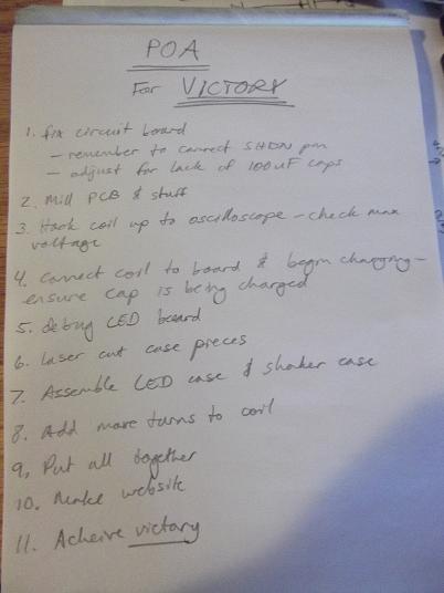
I was expecting victory. It says so on my Plan of Action.
Moving Forward by Rewinding
I made a new inductor coil with the same length and diameter as my previous iteration,
but just with a heck of a lot more turns on it. In total it took me about 1.5 hours to
wind my new inductor coil, but I was rewarded with about 2V coming out on the oscilloscope,
which was great! Unfortunately, the wire was very brittle and in retrospect, I should have
tried using some of the larger grade wire we had instead. More on that later.
After I rewound the coil I connected it to my board and started shaking. After about 15
minutes I got a reading of some voltage across my rectifier circuit, up to about 640 mV.
This was great, but it still didn't power my LED array.
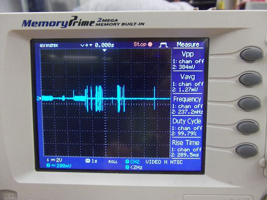
One of the better oscilloscope readings across my rectifier circuit. This one goes up to about 385 mV.
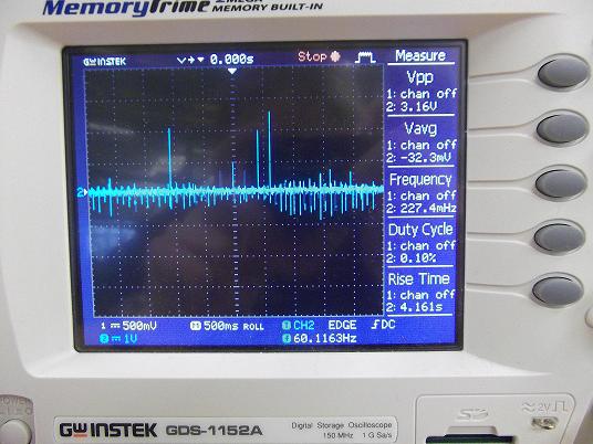
The oscilloscope reading of my new inductor coil - 3V! Yes!!!
Troubleshooting into a Wall
This, essentially, is where I have gotten stuck. Since my coil wires were so brittle, I
soldered them to some thicker wire and checked to make sure they were properly connected,
then connected my coil to the board. I shook the coil for over an hour and saw no appreciable
increase in the voltage across my capacitor, which I think disproves the fact that it
just took a long time to charge the capacitor. I am now not sure how to go about debugging
the board, because I don't really know what could be causing the problem, since I think
all the connections are solid.
In Conclusion
I just wanted to say that even though I was not able to get my final project to work,
I really enjoyed this class. I have learned so much in a single semester, its ridiculous.
Every time I've dropped the name of this class into casual conversation, I get impressed looks
or internship offers. (Hard to decide which I appreciate more.) And I haven't just learned
technical skills, either, although that's definitely a great part of it! In the final project
especially, I've learned how to manage my time, plan to acheive a workable goal, and
how to design something. Its been an invaluable experience and I can't say how grateful I am
for having the opportunity to take this class. Professor Gershenfeld, if you ever
need a TA for anything - molding and casting, water jetting, milling, sweeping the floor,
you name it - just let me know! I would take this class again and again and again, because
I know each time I would learn a whole range of new things, and I couldn't spend enough time on
it if I had 100 hours in a day.
Also I really wanted to thank all the TAs who have ever answered my questions, given me advice,
helped me get parts and supplies, or done things behind the scenes that I don't even know about.
It takes a lot of work to run a class of this magnitude, and I know it couldn't be done without you.
Thank you too to my classmates - its been a really fun semester learning with all of you, and I
feel like you've played an equal role in teaching me all that I've learned. But thanks most of
all for knocking my socks off every Monday with your crazy projects!!! And finally, thank you
Professor Gershenfeld for running this class every year. How to Make (Almost) Anything was the class
that best exemplified the spirit of MIT to me, and it was such a pleasure to be a part of it.
