Week 10: Mechanical and Machine Design
Got machine? This week's focus was on mechanical and machine design, especially as regards Jonathan Ward's MTM Snap machine. Each section was given the parts to make one machine, and assigned the task of constructing it and documenting the process. I was mainly involved in the first part of the process - milling out all of the parts. I've documented that, as well as the assembly of the framework which I was also present for. I spent the rest of the week working on my final project - I've created a separate page that will serve as my design log for this project.
Milling the Parts
We were given the Shopbot files all ready to run. Costanza had created a series of paths:
- Drill holes
- Mill pockets
- Inside profiles (some smaller pieces were nested inside the waste material of the larger pieces)
- Remaining profiles, going in 3 rounds (A,B,C), from outside to inside
There should be tabs on the profiles cut in Step 4. They can be the standard 0.25" x 0.125", and can be placed either manually or automatically. However, no tabs should be placed on faces that will have to be in contact with other faces; even after post-processing, this can still affect the snap-fit of some of the pieces.
The Shopbot toolpath is separated into 2 files: the first is the holes (Step 1 above) and the second contains all the milling passes. The division is because a separate drill bit should be used to cut the holes, followed by a single-flute end mill for the pockets and profiles. The exact feeds and speeds can be found on the MTM website.
Below are the two toolpath files:
|
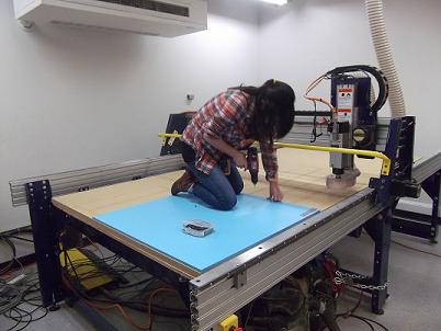
This is how we roll in MAS.863! Actually, its really important to ensure that the two pieces of plastic stock are flat on the sacrificial layer - especially when using the longer screws to secure the plastic to the surface, the plastic tends to bow upwards. Also, be very sure that the two pieces are flush against each other. We secured the first piece in the very corner (so that the machine's origin coincided with the origin of our cut file) and then adjusted the second piece to sit flush against it. When screwing down the pieces, first pre-drill holes in the plastic and then use the screws and sink them into the sacrificial layer. We put a screw in each corner to ensure the plastic pieces were properly aligned before adding more screws along the sides. Also be sure to put the screws close to the edges where necessary so that they don't interfere with the cut pattern. |
|
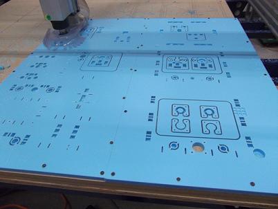
Here you can see the holes and pockets have just been completed and the mill is starting to cut the inner profiles. |
|
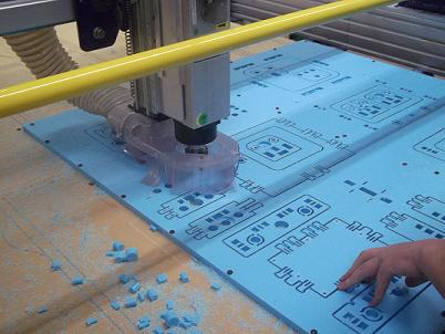
We followed behind the mill and removed the small pieces left behind (you can see a pile of them off to the side of the plastic stock); otherwise they just got sucked into the vacuum and made a loud noise as they hit the dust bin. |
Assembling the Frame
Once the pieces were milled, we had to do some post-processing to remove the pieces from the stock and to clean off the tabs. We found that a craft knife did a good job of removing the tabs and smoothing out the sides. In addition, for this part of the project John gave us an MTM machine that he had already built as a guide. We used that to follow the assembly of the outer frame and the bed (these we could do first before adding any of the mechanical hardware). It was important to follow the guide exactly because the frame is not symmetrical - one side has a different end hole for the threaded rod, etc. We also learned how to bend the snap-fit parts so that the pieces could be snapped together. I've added some images below:
|
|
|
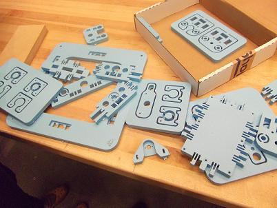
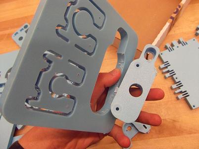
The pieces after being removed from the stock. |
Breaking the tabs off the parts. |
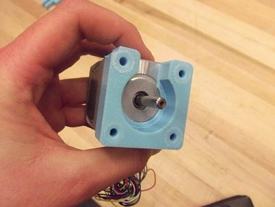
This piece of the spindle is a tight fit against the motor - hooray for tight tolerancing! |
|
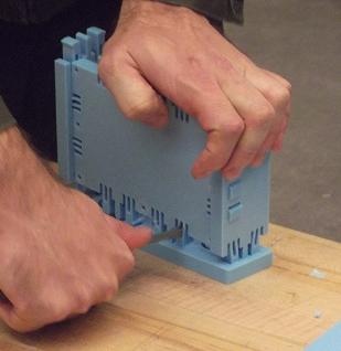
Here you can see John in the process of snapping two parts together. Applying force from the top, he works his way from one side to the other, using a flathead screwdriver to bend the snap-fit pieces into place. He goes one snap at a time until the entire side has been pressed flush. |
|