Week 2: Making a FabISP In-Circuit Programmer
This week's assignment was a significant change from the highly artistic, relatively low-tech world of laser cutting - instead of making our own creations, we were given the files to make a PCB board. This PCB board is called a FabISP in-circuit programmer, and we will be using it over the course of the semester to program all of our future microcontrollers. We were given the .png files with the circuitry and the outline of the board, as well as the program that we uploaded to the microcontroller, so this was a "cookbook" assignment. And since this is the first PCB we've made, I have pretty much no idea what we're doing, so bear with me as I try to explain what we did!
Milling the Board
We used a Roland Modelo tabletop mill to cut out the traces (the copper conduits that connect components on the board) and the board outline, and more Fab modules to convert the .png images to paths. The process is already pretty well documented on the website but there are a couple things to emphasize:
- If your mill is dull or you haven't cut deep enough (-0.2mm is usually adequate) then run two more passes - one at -0.2mm and one at -0.4mm.
- Use double-sided tape to mount the board to the substrate. Be VERY CAREFUL to keep it level so that the traces are cut evenly - don't overlap the tape or curl the corners.
- You can put the board anywhere on the substrate you want - pick a place, any place! You can set the x and y offsets on the Fab Module and hit the move button to see where you've placed the mill before you've started to cut.
- 1/32" mills are for cutting the outline, 1/64" cuts the traces.
- When lowering the mill onto the board, do it GENTLY - the tips are so fine that they can shatter if you just let them fall. Seriously, don't let go of the mills - they cost ~$25 a pop, and the lab instructor will get mad.
- When loosening the set screws on the mills, don't take them out all the way, and remember to loosen them both. I took one out all the way and it took a while to get it back in. Oops.
- You can always hit "View" to pause the job and look at it, and then hit "View" to resume the job, but the only way to cancel a job is to turn the machine off, then on, and then to hold the up and down buttons simultaneously.
- When the board is done, just scrape off the top with a steel ruler. Also, look for copper that should have been removed but wasn't - use an Exacto knife to very carefully scrape it off. You can peel off the copper you don't want, but be VERY CAREFUL not to take the traces off. Which leads me to my next point...
- Make multiple boards (you can fit 3 on a single piece) because you KNOW you're going to mess one up. Its going to happen - Murphy's Law is not a lie.
|
|
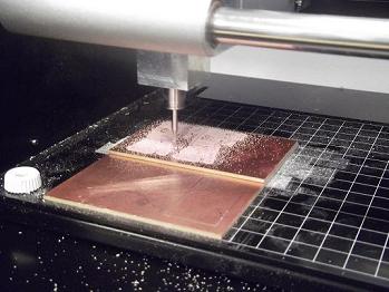
Here the Roland Modela is milling out the traces on the board. Notice the mess! (Thank goodness for handheld vacuum cleaners.) |
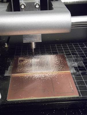
This is an image of the Roland Modela cutting out the outline of the boards. |
Stuffing the Board
Unlike a turkey, stuffing a board is very precise and tricky, and using force to get all that stuff on there is NOT recommended. No matter how much you want to, be gentle and careful and patient. To explain: stuffing a board means soldering all the components to it.
Soldering is a fine art, so here are some pointers - the rest is practice:
- SHINY AND SMOOTH - this is what you want your solder connections to look like. If they are dull and brittle, they may not be as robust a connection, and you should consider resoldering.
- Start with the smallest, shortest components and work your way out and up - this way, you won't accidentally hit components you've already soldered, either with your hand or the iron.
- Tack a component by placing some solder on the board in the right location, then reheating it and placing one end of the component in the solder. Then solder the other end.
- When you're tacking components in a line, think about what order you want to work in; if you're right handed, consider working from right to left, so that you get better access to the components with your right hand and the iron.
- Don't put too much solder down, because you don't want the components to be raised up above the board; the connection will not be as robust because the component will only be connected by solder to the copper on the board.
- Keep the tip covered in a fine layer of solder.
- Solder flows towards heat, so heat with the iron the parts you want to solder before adding it.
I found soldering the USB port to be the most difficult part of making the FabISP, so I feel it deserves some explanation. On my first board, my USB port had a bump on the bottom so it would not sit flush with the surface of the PCB; not knowing any better, I tried to solder it on anyway, which, of course, didn't work too well because the solder wouldn't bridge the height gap between the pins on the port and the traces on the board. So, my first piece of advice is:
- Find a USB port that sits flush on your board! Also:
- Tack one corner of the USB port onto the board, then apply a large lump of solder onto all the pins. Trust me (or, if you don't trust me, trust Neil, who suggested using this method in the first place) - once the solder is on the pins, use copper ribbon to remove the lump. When you do, just enough solder will be left to connect the pins to their respective traces without any kind of solder bridge whatsoever. It comes out much prettier than if you had tried to do each one individually!
- Don't solder the other three corners of the port until after you've uploaded the program and are sure the board works! You may need to make some troubleshooting adjustments to the USB port's connections/placement on the PCB and it will be much easier to adjust if you haven't completely secured it to the board yet.
|
|
|
|
|
|
|
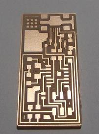
This is the completely milled board, before the components are added. |
|
|
|
|
|
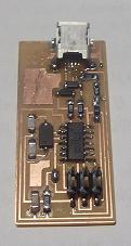
After stuffing, the board looks pretty pro! |
Programming the FabISP
Programming the FabISP turned out to be a lot more complicated than I thought it was going to be, and I had to pull directions together from two different places, so I wanted to consolidate them here so that in future it would be easier to do this. Before following these instructions, you will need to download the necessary software: WinAVR for Windows, and CrossPack for Macs. You will also need to download the firmware.zip file (and unzip it) which contains the program you want to upload to the board. Once you've done that, follow these instructions:
- Plug in the USB cable to the USB connector on the FabISP to give it power; then plug in the AVRISP Mk II to the 6-pin male connector; make sure the red cord is aligned with the first (MISO) pin on the connector.
- Open the firmware folder and find the Makefile document - open it in Notepad. Near the top of the document is a line of code beginning with avrdude and indicating that some coding will have to be changed according to the devices used. If you are using an AVRISP MkII to upload the code to your FabISP, then change the line of code to read: avrdude -p t44 -c avrispmkii -P usb -U lfuse:w:0x7E:m
- Open the Cygwin command line and navigate to the directory where your main.hex file (inside the firmware folder) is located.
- Enter in this series of commands:
make clean
make hex
make fuse
make program
- The light on the AVRISP MkII should turn green and your FabISP should be ready to go. At this point, you need to remove the two solder jumpers and then you're good to go!
 |
 |
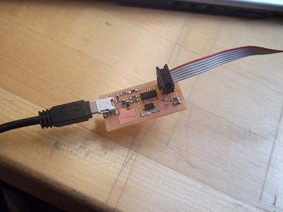
Here's the board plugged into the AVRISP MkII and the USB cable providing power to the PCB. |
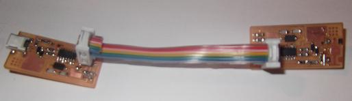
This is how the FabISP will be used to connect to other boards to program them in future. |
Making a Rainbow Bridge!
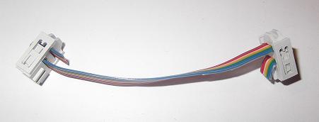
That probably isn't the technical term for what I'm talking about, which is the connector cable that you will use to connect your FabISP to other PCBs that you want to program. I call it the rainbow bridge (or the Rainbow Connection) because the 6-wire cable is rainbow-colored. Its very easy to make - just cut about 3 inches (seriously, that's all you need - any more and it will just be inconvenient) and then use a vise to clamp a 6-pin female connector on each end of the cable. And be sure that the connectors are oriented in the same direction (see pictures below)!
 |
 |
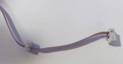
This is not good. In fact, it pretty much means you're not paying attention at all. The connectors need to be ALIGNED! |
This is much better. Notice how short the cable is - you really don't need too much length! |