Oh the shame.
Week 7: Input Devices
This week was an introduction to various input devices that are commonly used in electronics. I personally found it very challenging just to get the software to work on a Windows operating system, however, so most of this page will chronicle what I did to get the software to work - I had proportionately less time to work on different input devices, as a result.
Hopefully this page will help people struggling to get their software to work, because I've found a lot of non-Mac users have more difficulty with Python than normal...Also, I found documentation a little thin on the ground in general for this week, so hopefully this will clarify some things.
Building and Programming the Boards
This was a straightforward task - I chose to make Neil's step-response board (hello.load.45.c) that would measure the capacitance between two copper pads, indicating whether someone was touching them or not.
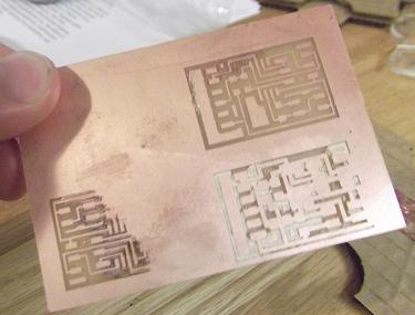
My first round of milling, however, was proof that just because you've used a machine for multiple weeks, it doesn't mean that you can just skip steps like a pro. I ended up cutting my traces unevenly (and then too deeply); I had to stop and remember to zero my endmill before each cut, even for cuts on the same piece of board. (I have put up evidence of my blunder below.)
In terms of programming the board, I went with just using Neil's code without any modifications. One note of caution to people who are modifying previous Make files for this code: DOUBLE CHECK THE MICROCONTROLLER YOU ARE USING. If you're using a different microcontroller to what is listed on the Makefile, it won't work until you change every instance of the microcontroller to reference the correct one. I did that and wasted about an hour trying to figure out what went wrong. Oops.
|
Oh the shame. |
Running the Python Interface
Here is where the trouble begins. I've numbered the steps I took in my problem-solving process below - try any of them if you are having similar difficulties! Here's the situation: I was working in Windows with Python 2.6.6, and when I tried to enter "python hello.load.45.py" into my Cygwin command line, I was told that the Tkinter module couldn't be found. Tkinter is a graphics module in Python that is used to create the rectangle display showing the capacitance read by the board. (Note: I had already installed Pyserial, term.py and rx.py, which are all needed to run the interface software.)
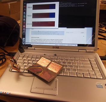
With this last step, I finally had my program working! Some images below show my setup and the display.
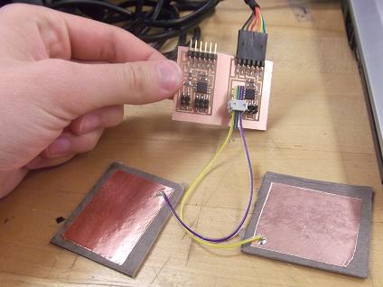
I was unsure about how many copper pads we needed and what configuration we needed to use - I started with each wire connected to an individual copper pad. Then I figured out that only two of the pads were needed, so I re-did my copper pads.
|
|
It works! This shows my original 4-pad configuration, as well. |
After hacking apart my 4 pads to get 2. |
|
|
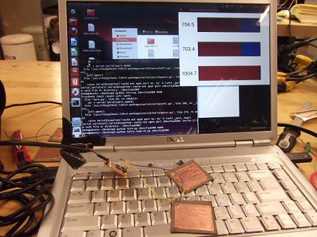
The display when the copper pads aren't connected. |
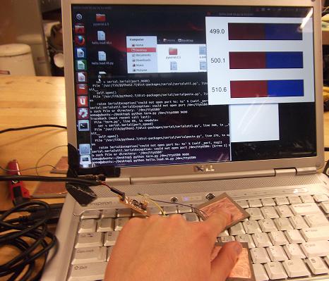
The display when the copper pads are both connected. |