This was a pretty exciting week because we were given a lot of different starting points for developing output devices! The assignment was to build and program a board that gave some sort of output, whether it was an LED, an LCD screen, video output or sound. I decided to start out with Prof. Gershenfeld's basic Charlieplexed LED array and his speaker board (so that I would at least have SOMETHING to show at the end of the week) and then started hacking the code to play with it more myself!
Charlieplexing
Before I dive into the making and programming of my LED array board, I wanted to give a brief explanation of Charlieplexing. Prof. Gershenfeld gave us a link to the explanation by the man behind the magic, Charles Allen, but I found this to be a bit above my head, so I found an Instructable that gave an excellent description for the layman. To summarize:
Charlieplexing is a technique that allows you to control more LEDs than you have pins for on your microcontroller. If you have n pins available, you can usually control an array of n * (n-1) LEDs. This is really powerful, especially with the more LEDs you add to your array, and you can light any LED individually or in a pattern as you desire.
Charlieplexing relies on the fact that LEDs are unidirectional - current can only flow forward in an LED. So if you connect two LEDs in parallel, pointed in opposite directions, then you can drive one at a time by reversing the direction of the current. (If you had two pins connected to this series circuit, you would then reverse which one had an output of 1 (on) and which had 0 (off) to change current direction.) This is called "complementary drive".
You can expand on this idea by creating multiple parallel circuits with LEDs as described above, and activate individual LEDs using the microcontroller pins as either on, off, or high-impedence.
High-impedence is a technical term referring to when an output pin is programmed to be an input pin - this is done if you want to turn a pin off while running the circuit on two other pins. High-impedence means that the resistance of the pin is set very high, so that the current flowing through it is extremely low to negligible.
Making and Programming the LED Array
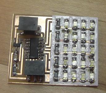
Making the LED board was not quite standard, because one of Prof. Gershenfeld's colleagues had developed an ingenious way to use some vinyl-cut epoxy and copper traces to make a 2-layer board that enabled us to use 1/4 of the resistors we'd need otherwise! I've put the pictures in below with explanations of each step.
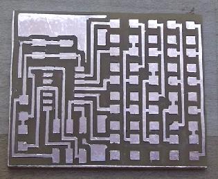
This is immediately after milling out the board. One thing to note is that there is a good deal of copper residue that gets left behind after milling all the close traces. It takes a bit of work to get all the strings of copper off, and you have to be careful not to use sandpaper or a metal ruler too aggressively, because you risk taking all the traces off too. I used an Exacto knife to cut pieces off more precisely where necessary. It can be time consuming, but this step is really important because you don't want copper floating around and making connections between traces when there shouldn't be any!
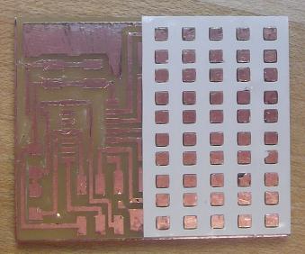
Now the epoxy layer that was cut on the vinyl-cutter has been overlaid on the circuit board. It is worth noting that the best way to do this step is to transfer the entire epoxy layer (including all the little squares) to the PCB board, and then to weed out the squares individually afterwards. This ensures that the epoxy layer is firmly adhered to the PCB board before you start handling it too much in trying to remove the smaller squares.
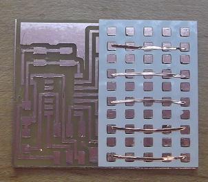
Laying the copper traces can take a bit of hand-eye coordination, but just take it slow. Also take careful note of which rows the copper traces go on - you don't want to get it backwards. Also, I found it useful to lay one end of the copper down, hold it with a finger, and then to pivot the trace to its proper location.
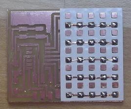
Again, all this takes is a little patience - you'll feel as though the board is much more secure after soldering all the copper pads on the PCB board to the traces on the next layer.
The only hard part about stuffing the board is getting all the LEDs on!
Once the board was made, it was easy to load Prof. Gershenfeld's code onto the microcontroller, and it worked just fine. But I wanted to play with the code a little bit, so I figured out how each LED was accessed in the C code, and from there it was easy to manipulate the array to get any pattern I wanted. I figured out that the line of code that flashed each LED referred to the two pins used to light each LED:
flash(B,C,delay)
You can think of the array as a grid with coordinates that refer to each LED individually, as follows:
B,A
C,A
D,A
E,A
A,B
C,B
D,B
E,B
A,C
B,C
D,C
E,C
A,D
B,D
C,D
E,D
A,E
B,E
C,E
D,E
The letters each refer to a pin on the microcontroller; the first pin in the pair is the pin that is turned on, the second pin is the one that is turned off. All the other pins are in high-impedence mode, and so the current flows from the first pin to the second pin, lighting the corresponding LED.
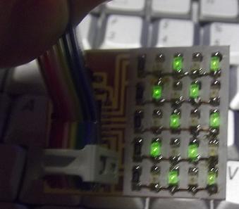
Once I had this figured out, it was easy enough to program different patterns onto my board. For instance, I lit up only every other LED:
I also made the Pi symbol on my board (you can also see a video of it):
Making and Programming the Speaker Board
I wanted to make the speaker because I was equally interested in hacking into the code that ran the speaker, to see if I could play a popular tune I knew. So far no success on that front, but I did nonetheless make and program the board, and I hacked into the code insofar as I made it sound even WORSE than it did before!
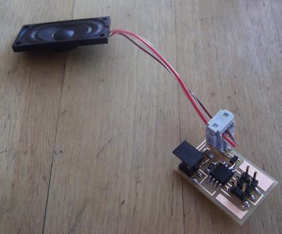
Milling the board was pretty straightforward, as was stuffing it. The slightly complicated part came with getting the speaker correctly connected to the header, and the header correctly attached to the board. The image below should show pretty clearly how that should be done (you only need two wires instead of four).
When I looked at Prof. Gershenfeld's code, I managed to replace the linear feedback shift register that generated pseudo-random numbers, and put a basic linear function that generated one sound in its place. Whoopie. I have just removed all the complex, intricate aspects of the code and given it my own, simplistic, boring character. Actually, this is the first step - I hope to figure out how to play a series of notes soon. In the meantime, I have embedded this video of my banshee speaker for your delight: