3. FabISP In-Circuit Programmer

This week, we covered electronics production, including PCB production and assembly. The project for the week was to construct our own FabISP board, which is an in-circuit programmer for AVR microcontrollers. In other words, we’ll be able to program the microcontrollers on the other boards we make throughout the semester.
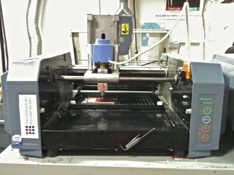
We covered two ways to make circuit boards in the shop. The first is to mill the board using the Modela machine. It’s a relatively slow method (about 10 minutes per square inch), but easy to use.
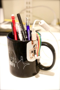
Circuit stickers are awesome.
The downside of the machine is that the endmills can wear out easily, especially when it’s being used by twenty people. The real art to a Modela is setting the proper speed and depth. When I was using the Modela, there was a tendency for one end of the board to get milled deeper than the other end. We had to compensate by increasing the z-depth from the default 0.1 mm to 0.14 mm. For me, I found that lowering the speed from the default 4 mm/s to 3.7 mm/s helped tremendously. When the speed is set too high, the endmill tends to tear up the board, making it bumpy and uneven.
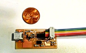
Stuffing the board turned out to be a challenge all on its own. I had done an analog electronics class for two terms at Caltech, so I theoretically knew how to solder, but I was not prepared for handling such small components. Here’s the finished board, with a penny next to it for scale. I actually lost a capacitor by accidentally breathing on it.
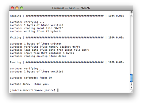
Thankfully, I managed to program my board the first time through. I borrowed my officemate’s FabISP (thanks Akito!) from last year to program my board. At first, I kept on getting an rc=-1 connection-status-not-found error, but that was because I did not line up the six-pin cable correctly. Once correctly oriented, programming the board was straight-forward.
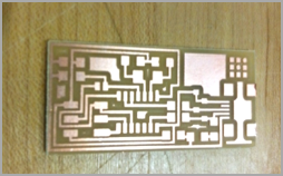
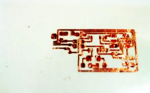
Later that day, Jie gave a demo for vinyl-cut circuits. Instead of milling a board, you can use the vinyl cutter to cut out the circuit design on copper tape. Instead of tens of minutes, it takes seconds to cut a board. The hard part, however, is in weeding the tape to get rid of unwanted copper. It took me about 40 minutes to weed my board.
I love vinyl-cut circuits. There’s something “real” about the circuit; the form factor is much more familiar. After all, it’s just a pretty copper sticker. It’s great for very rapid prototyping, one can just cut out stripes of copper tape and arrange components!
Vinyl-cut circuits has downsides too, however. They’re much more delicate than the milled boards, and with a fine design like this one, it’s easy for the copper to break, especially while soldering and plugging/unplugging the ribbon cable.
I soldered on the components, and held my breath, and... it refuses to be programmed.
I entered the darkness that is hardware debugging.
-
1)Check all your soldering joints. Make sure they’re shiny.
-
2)Multimeter is your friend. You can use it to check that the chip is getting powered (5 V on the Vcc pin). You can also use the continuity mode while the circuit is unpowered to check that all your pins are correctly connected. I love the multimeter. Hardware debugging is so satisfying because you can read the actual electrical signals. With software debugging, there’s always the chance that the debugger or the compiler has an error. Hardware debugging feels more “down to earth”.
-
3)Check your circuit against the schematic to make sure you’ve stuffed the board correctly. In my case, I discovered that I made a mistake while weeding and accidentally left off one of the pins on the ATtiny44.
-
4)If the usb connector is lifting up some of your traces, hold it down. That eventually got my board to program.
Oh, the sweet, sweet sight of victory.
Tips and Advice:
Modela Machine
Setup:
-
1.Press the View button to bring the bed out for view. Sweep down the bed for debris. Using double-stick tape, attach a sacrificial board to the bed. Now put on the new board, also with double-stick tape on the bottom. Press down hard.
-
2.Put in the end-mill. 1/64” for milling, 1/32” for cutting out the exterior of the board.
-
3.Open the fab module. Open the png -> Modela option. Select the right preset on the top. In order to make the path, there are some settings:
Diameter - diameter of the tip of the end-mill.
Offsets - number of outline traces. The greater the number, the more area gets milled.
Overlap - how much each trace overlaps the previous trace.
Threshold (0-1) - threshold for cutting. 0.5 means the program contains gray to be the cutting line.
Error (pixels) - how closely the traces follow the original design. 1.1 is a default setting that gives some anti-aliasing.
Z - how far down the the machine cuts. This is a very important setting. You may need to set it higher than the default 0.1 mm. My officemate swears by a depth of 0.12 mm and a speed of 1.7. But it depends on the day and the age of the end mill and how happy the machine is. A general lesson around the shop (and in life): don’t expect it to work great on the first try.
-
4.Make the rml. Estimate a good starting location (the grid pattern on the bed are in cm), and move the end-mill there. It’s very important to get the end-mill zero’ed property on the z axis. Holding the end-mill with one hand, loosen the two screws holding the end-mill in place, and let it gently drop down until it hits the board. Next, holding down the end-mill against the board with one hand, tighten the screws with the other. The end-mill will have a tendency to move back up while you’re screwing it in, so make sure you hold it down. Also, don’t tighten the two screws serially. Go back and forth to make sure the pressure is evenly applied to the end-mill.
-
5.In addition, make sure the head holding the end-mill isn’t too low or too high. Use the up/down arrows for adjustment (you’d have to hold down the buttons). Too much end-mill sticking out, and it might snap. Too little, and you might not have enough room to move up and down while milling.
-
6.The default speed is 4 mm/s. For a new end-mill, try 3.5. Again, I found going slower makes for a better, smoother board. Send the job to the Modela.
-
7.While the board is being milled, make sure you can see some white stuff (the underlying plastic) coming out. If the traces are still shiny on the bottom, you’re not cutting deep enough.
-
8.Once the board has been milled, switch end-mills to cut out the outside. Make sure to load a separate png.
Soldering
-
-Make sure the soldering iron is hot and the tip is clean. I like to make sure that it sizzles on the wet sponge before using it. The size of the tip also makes a big difference. There was one fine tipped iron in E15-043, it made soldering the tiny legs on the tinyt44 so much easier.
-
-The components are tiny. Tweezers are your friends.
-
-Ideally, I’d have three hands so one can hold the tweezers, one can hold the solder, and one can hold the iron. Lacking that, I find it easiest to 1) put some solder on one of the pads on the circuit 2) place the component over the pad with tweezers and re-melt the solder to pin down the component 3) solder the remaining legs of the components with the solder-with-one-hand-iron-with-the-other approach 4) go back to the first leg and solder it properly.
-
-Be patient - it takes a few seconds for the solder to flow. At first the solder will ball up, but then, when it gets hot enough, it’ll flow gracefully down to the copper. It’s a pretty magical moment.
-
-For super tiny legs, like the usb connector, just liberally apply solder, then siphon off the extra with the copper braid. It works like magic.
Vinyl Cutter
-
-For circuits, set an offset of 0.25 mm on the fab module when making the path. This will enlarge the path and make it easier to weed.
-
-The velocity is pretty good at 2 cm/s. You’ll have to play with the force to get it to cut just deep enough. Too fast, and the blade will rip through the copper. If you can see the tape lifting while it’s being cut, the force is set too high.
Setup:
-
1.Check that the cutting blade is sticking out by the right amount. Only the very tip should be out - about 1 mm or so.
-
2.If the machine is asleep, press any of the direction buttons to wake it up and move the head to the very right side. Make sure the wheels are within the width of the copper tape while still being on the white line. Pull the lever back to unlock the wheels, load the tape, then pull the lever up to lock. Use the up and down arrows to select the “Piece” setting. Press enter. The head should move to the front of the tape.
-
3.Load the fab module. Pick the png -> vinyl cutter option to make the path and .rml file. When done cutting, hold the down arrow button to extract the tape.
-
4.To move the origin to somewhere other than the lower corner of the tape, use the direction arrows on the machine. Hold down the <origin> button to set the location. Keep in mind that there’s about an inch of margin around the tape that the machine can’t access.
-
5.Press the <pause> button to pause the work mid-cutting. Press <pause> again to continue, or <enter> to exit.
Transfer:
-
1.Cut a piece of masking tape larger than the circuit. Place the tape over the circuit and press down. Now you should be able to peel off the masking tape with the copper attached to it. Don’t worry if you’re lifting off the entire outer area of the circuit instead of individual components. That’ll come later with the weeding.
-
2.Put the masking tape sticking side down (with the copper stuck on the bottom) on the final destination. This time, press down really hard. The copper uses a pressure-sensitive adhesive.
-
3.Finally, peel off the tape using shear force (not straight up!). Now you’re ready to weed the copper with a pair (or two) of tweezers. Have faith and pull up - the extra copper will have a tendency to follow the cut-patterns and should come off fairly easily.
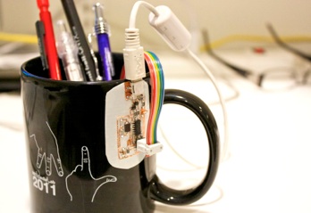
I’ve got a circuit cup!