FabISP
The FabISP is an in-system programmer for microcontrollers. As per this week's assignment, I constructed my own following the design provided by David Mellis
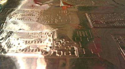
Step 1 | Milling the board on the Modela
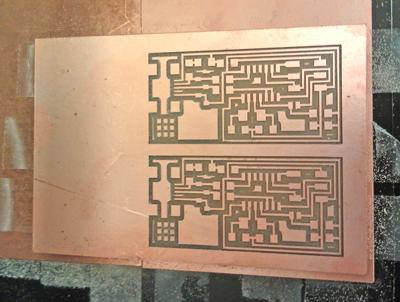
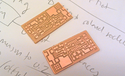
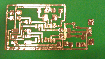
Roughly following these instructions, I used the Roland Modela to mill the traces and cut out the boards from a sheet of copper plated plastic. I cut the traces with the fab module presets, with a z depth of -0.1 mm using a 1/64" endmill.
I had to adjust the z depth several times to cut out the boards themselves. I switched to the 1/32" endmill and initially had the depth set to -0.3, but found that this was much too shallow. I adjusted the z-depth to -1.0 and the boards cut out nicely.
Step 2 | Stuffing the board
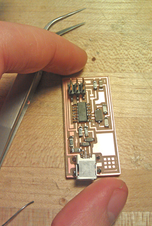
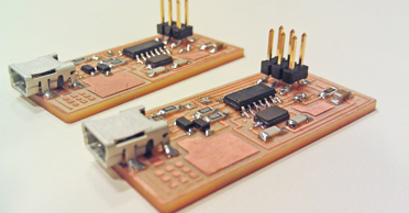
After the boards were cut, I followed the provided schematic to select the components. I started by soldering the shortest components first and worked up to the taller ones. To solder the pins of the attiny and usb connector I used the soldering iron to brush on solder rather than heating up the pins directly. I didn't have much luck with the copper braid, so instead I just used the soldering iron to remove any solder bridges.
Step 3 | Programing the board
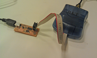
I downloaded the firmware and installed CrossPack on my Mac. After unzipping the firmware, I modified the makefile on line AVRDUDE = avrdude -c usbtiny -p to support the AVRISP mkII programmer by replacing -c usbtiny with -c avrispmkii -P usb and saved the changes.
I plugged the board into my computer via the usb connector, plugged the 6 pin connector of the programmer into the board and connected the programmer to my computer. When the light on the programmer turned green, I opened terminal, navigated to the directory containing the firmware and ran make program.
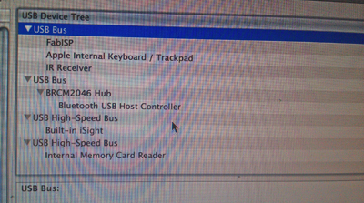
I had soldered two boards so after programing them both, I removed the solder jumpers and checked to make sure they were working by confirming that they registered as usb devices in the system profiler. The first board didn't register inititally, so I used a multimeter to check the pin connections on the ATTiny and found that one pin was not connected. I re-soldered it and it registered.
Bonus Round | Cutting a circuit with the vinyl cutter
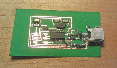
Jie Qi was nice enough to demonstrate how to cut a circuit with the Roland Vinyl cutter, so I attempted to create a version of the FabISP on paper.
After several attempts, I successfully cut out several of the circuits with the Roland Vinyl cutter by using a speed of 2.5 and a force of 67. I transferred one of the circuits to a piece of paper and weeded it.
Soldering onto paper and adhesive backed copper was considerably more challenging than soldering to the milled boards. I had to be sure not to lift off the traces when I soldered in the components as the iron would melt the adhesive from the copper as well as the solder. I achieved this by mainly touching the iron to the components and using that to transfer the solder to the copper
The programing process was identical to the milled boards with one exception. I didn't solder 2x3 pin header to the paper board as I was afraid that the act of plugging it in would lift the traces from the paper. Instead I just held it on while I programmed the board, which seemed to work fine.