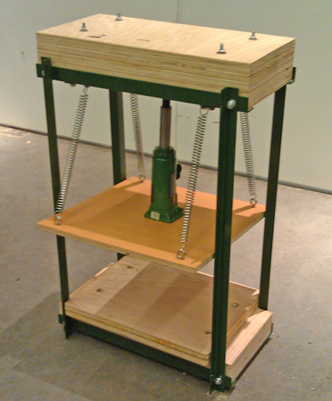
Hydraulic Letterpress
In my research group we've been experimenting with making our own paper and embedding electronic components and conductive materials in the sheets. In order to effectively press large amounts of paper for the paper making process, we needed a pressing mechanism. We also thought that it might be interesting to experiment with printing with conductive inks with movable type. As a result, I decided to make a hydraulic letterpress that will eventually allow us to do both. My primary goal for this project was to design the press and assemble the frame. Some additional refinements still need to be made.
Step 1 | Designing the model in Solid Works
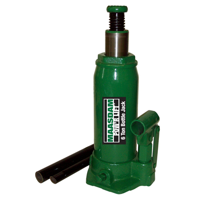
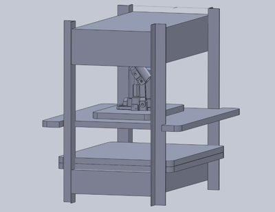
I researched several different designs for DIY letterpresses that I found online. The most interesting ones were those that were created by modifying a hydraulic shop press. I decided to design around that concept. The original concept was comprised of 4 steel angle beams for the uprights, 4 steel crossbars and sheets of laminated plywood for the base, top and platen. I purchased single hydraulic car bottle jack that I then incorporated into my design. After some initial sketches on paper, I mocked up the entire assembly in Solid Works.
Step 2 | Building a miniature version
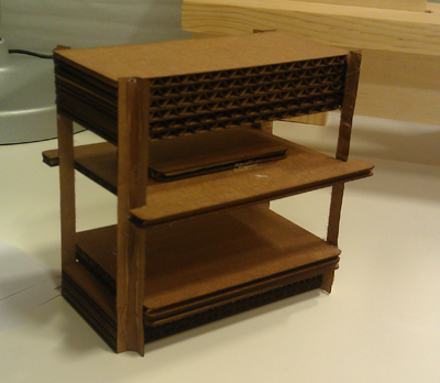
I cut pieces for a 1/20th scale -model on the laser cutter out of cardboard and assembled it. I noticed that the platen was a bit too snug and didn't move freely on the miniature so I modified it in the solid works file and made some other small adjustments for stability and integrity.
Step 3 | Cutting platen on the shopbot
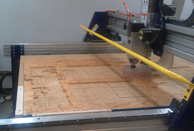
I purchased a sheet of 3/4 in. x 4 ft. x 8 ft. birch plywood at Home Depot to build the wooden parts. I used the shopbot to cut the bottom and top platens. To save on material for the sheets that comprised the base and top, I used the table saw.
Step 4 | Laminating the plywood

Using a brush and wood glue, I glued the sheets of plywood together for the base, top and bottom platen. I then clamped the sheets together and let them dry for 24 hours. The base and top measured 23.5" x 11.75" and were comprised of 6 and 4 sheets of laminated plywood respectively. The bottom platen measured 19.25" x 15" and was comprised of 2 sheets of laminated plywood. After the sheets were dry, I sanded the edges and removed the excess glue.
Step 5 | Cutting and drilling the steel angle
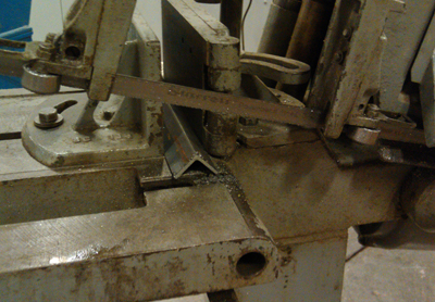
I purchased 4 1.25" x 48" lengths of steel angle for the upright beams and 2 1.5" x 48" lengths for the crossbeams. I cut the steel angle to size on the bandsaw. The crossbeams were cut to 24" long and the uprights were cut to 35". I used the drill press and a step drill to drill 25/64th inch holes .75 Ň inches and 4" inches in on each side of the crossbeams. The uprights had holes 1.5" in on each end.
Step 6 | Cutting the secondary crossbeams

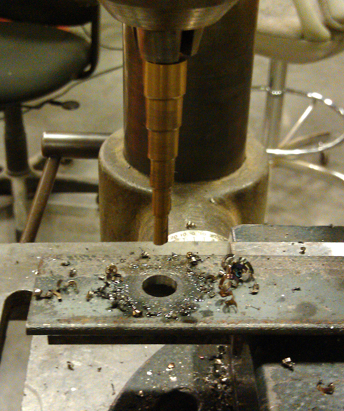
I used the OMAX water jet to cut the secondary crossbeams that would support the base and top. The supports were cut out of 1/8" steel and were 1.5"x 12.25" with 25/64th inch holes .75 Ň inches and 4" inches in on each side to match the crossbeams.
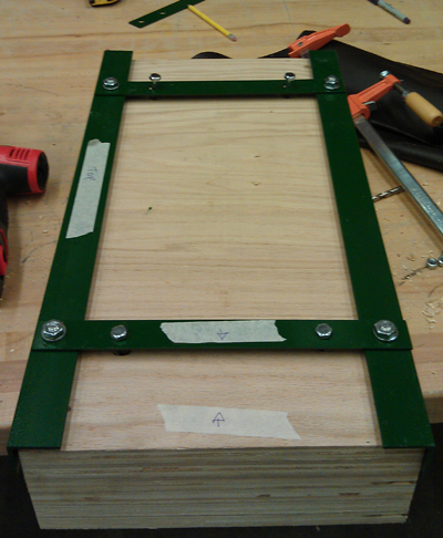
Step 6 | Drilling the wood

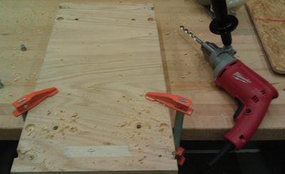
I assembled the frame with .88 mm hex bolts and lock washers to test the measurements and then measured holes for the wood components. I had to mill notches for the heads of the bolts out of the base and to so that they would sit flush against the crossbeams. After drilling, I tested the fit again.
Step 7 | Painting the steel

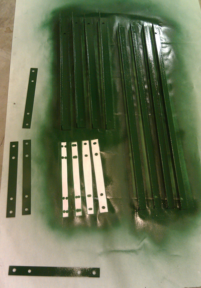
I removed all rust and cleaned the steel with a square of scotchbrite and de-burred all of the holes. I then painted it with rustproofing green spray paint to match the jack.
Step 7 | Assembly and future steps
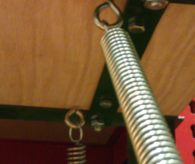
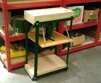
I assembled the entire frame and I bolted in 4 sets of eye bolts to the top and top platen and attached 4 tension springs to each. The tension springs allow the jack to compress when the pressure valve is released. The bottle jack was placed in the center of the platen and is currently held in via tension. Next week I plan to cut a pair of steel plates to mount the surface and bottom of the jack on the platen directly and help to evenly distribute the weight. The top platen also needs to be supplemented by adding an additional layer of laminate. Finally all wooden parts need to be re-sanded and finished with polyurethane to guard against moisture. Then, it's on to creating and casting a set of moveable type!
Special thanks to Tom for teaching me to use the bandsaw and drill press, Jie and Sam for their amazing help in construction and to Martin for helping me to use the table saw and letting me use his very nice power tools. This was a group effort!