Embedded Programming
For this project I first attempted to complete the basic board modification, and then took it a step farther, building a board to control a small DC rotary motor.
Step 1 | Modifying the Board Design
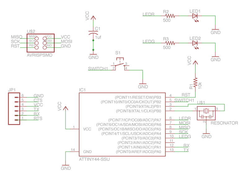
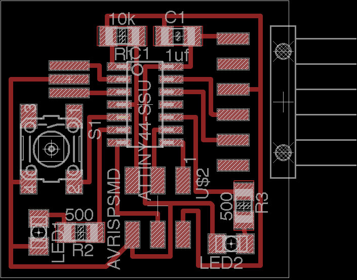
Using eagle, I modified the hello.ftdi board design to include two leds, two 550 ohm resistors and a switch. Eagle Schematic and Eagle Board
Step 2 | Milling and Stuffing
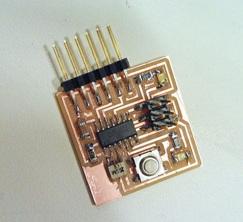
I milled the board on the modela, but had a few issues with fine traces remaining between the footprints for the attiny. I scraped these off with an exacto knife after failing to remove them with a metal rule. The board got a bit banged up as a result of this
Step 3 | Programming the button and LEDs
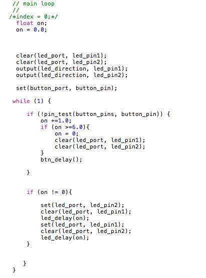
I wrote a basic blink program with c using the existing code as a reference point and attempted to upload it to the board via my fabISP. I had a few issues with not setting pins as outputs and a broken LED that I had to replace, but after troubleshooting with the multimeter and re-soldering a few connections, the board was successfully programmed. I played with the program a bit more, and wrote a function that would toggle the speed of the blinking lights progressively faster with each button push, similar to a bike light function. .png file.
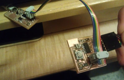
Step 4 |Finished Board
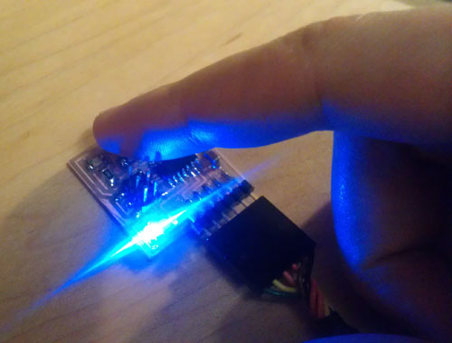
Here's a quick video of the finished board in action. Apologies for the shaky camera, I had to interact with it and hold my camera at the same time..
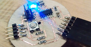
Extension- Step 1 | Board 2


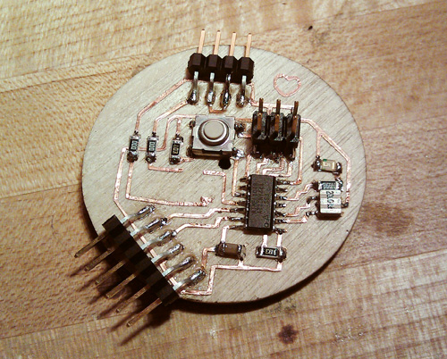
I decided to attempt a vinyl cut board on wood that would turn a motor. I modified my original schematic to include a 4 pin header for external power and a mosfet to delegate the power signal.
Step 2 | Cutting and Weeding

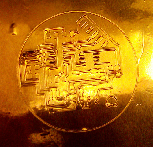

I successfully cut the board with a force of 80-81, though it took several tries. I mounted it on a small disc of wood that I cut with the lasercutter and weeded it. I found that weeding on wood was much faster than weeding on paper.
Step 3 | Stuffing and Programming
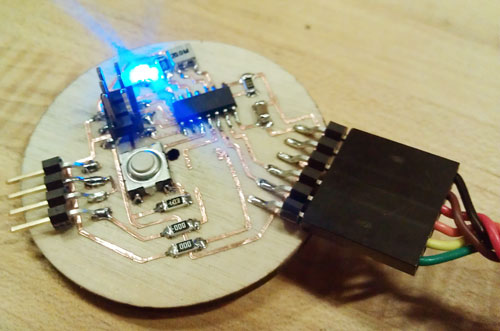
With some difficulty, I stuffed the board. I was unable to locate the correct mosfet that I required for the motor, so I added in the other components and ordered the mosfet. I found the soldering iron only minimally scorched the wood. I then superglued the headers to the board so they would not pull the traces off when plugged in, connected it to the fabISP and uploaded a program to test it. Once I have the correct mosfet, I should be able to use it to power and control a small motor.
Thanks to Dave for his help in programming, Ed for his assistance in debugging and Adam for helping me out with understanding motors.