Official Assignment Description: 'build a wired &/or wireless network with at least two nodes'
For sometime now I have been working towards implementing an autopilot on a small remote-controlled airplane I made a year and a half ago. An important part of the system will be the RF hardware and communication software between the pilot and the aircraft; these topics will be the focus of this week's project.
Ultimately, I need fast, long-range, light-weight, and robust wireless data transfer. For now I'm working with two Xbee wireless transceivers that cost about $20 each and operate at 2.4GHz. Although they are a little pricey, the modules seem to be robust and easy to use; they also come in a modular package which can easily be exchanged for more powerful versions (in order to acheive longer range). Unfortunately, time is a little tight this week, so all prototyping was done with COTS Arduino boards. Software was done from scratch.
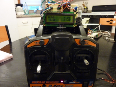
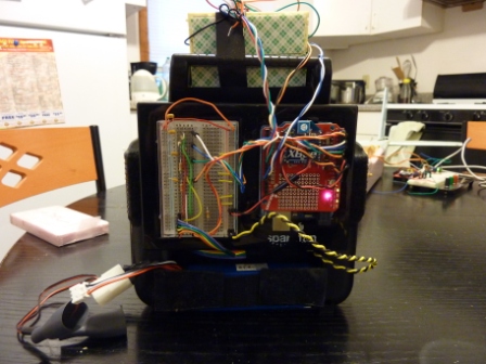
Step 1: Open up my old remote controller and solder wires to potentiometer pins; this allows the Arduino on the back
of the remote controller to read analog voltages which are proportional to the pilot's control stick movements. Analog low pass
filters included to reduce noise, and use an old LiPo for power. Add an LCD screen for the pilot.
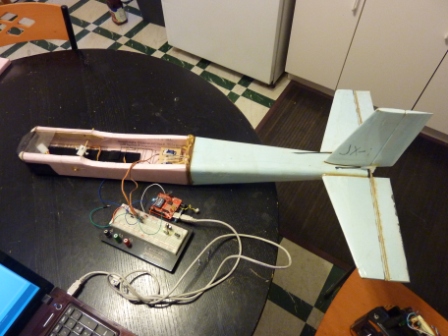
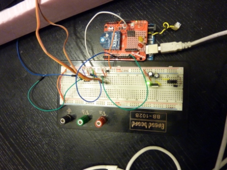
Step 2: Pull out (most) of my old airplane (JX-1) and setup wireless modules. Note that the USB cable is for power only.
Step 3: Write a code for the transmitter. This reads in analog signals from the 'roll' 'pitch' 'yaw' and 'throttle' commands
as well as digital signals from two switches. This information is then printed to the serial port at 9600 BAUD in a string
approx 40 characters long.
quad_trans.pde
Step 4: Write code for the receiver. This reads in the string from the transmitter and parses it into pulse width commands
for servos. The arduino's interrupt-based Servo.h library is used here to ensure pulses are delivered to servoes at approx 50Hz;
this works very well, as long as you do not use the SerialSoft.h library (which disables interrupts).
servo_interrupt_test.pde
Step 5: Put it all together and test. In the video, you can see the servos (hidden) responding wirelessly to stick movements
on the transmitter. One stick moves the 'elevator' (up down flap) and the other stick moves the 'rudder' (side to side flap).
Other channels are available to control ailerons, throttle, etc.