FINAL PROJECT: MINIMAL SURFACE AS RESPONSIVE FURNITURE
Intent:
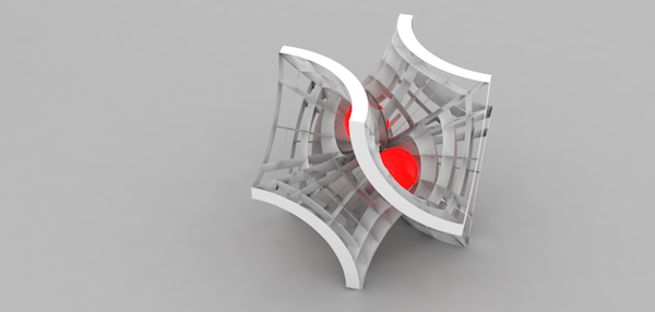
In the 3D printing week, I started getting interested minimal surfaces (they just look so cool!), but I noticed that almost every example of a fabricated minimal surface was 3D-printed and on the scale of a toy or paperweight. So, I thought it would be exciting to make a BIG minimal surface. Also I wanted my final project to be something challenging and hopefully, in some way, not done before and I knew this certainly would be difficult.
(image sources: William Schaecher, Shapeways; Torolf Sauermann, Evolution of Genius, Jotero)
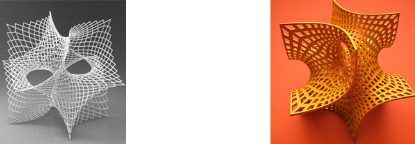
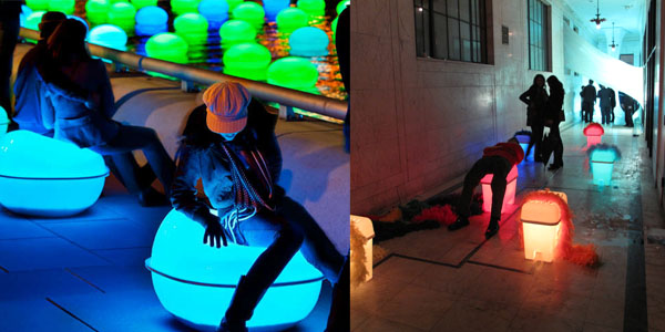
But what purpose would it fulfill? Well I thought that the batwing shape (pictured above) could provide an interesting 2-4 seat bench. The idea of being able to sit on a mathematical function just seemed too cool. In addition, I started looking at responsive furniture (Meejin Yoon's Light Drift, Rudolphe el-Khoury's Chameleon Lounge) and thought that doing a responsive light system might be exciting.
Form Design:
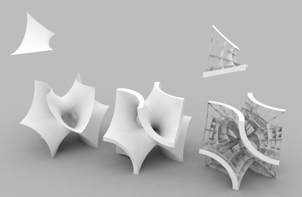
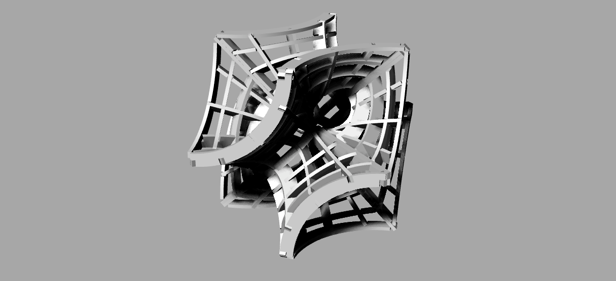
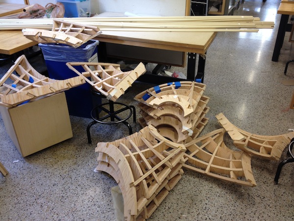
After a good amount of research and playing around with geometry, I managed to figure out a simple (non-scripted) method for drawing the batwing. And as it turned out, the shape could be reduced to a single unit that is repeated 12 times. So, naturally, I thought this was a perfect solution for the fabrication of the structure.
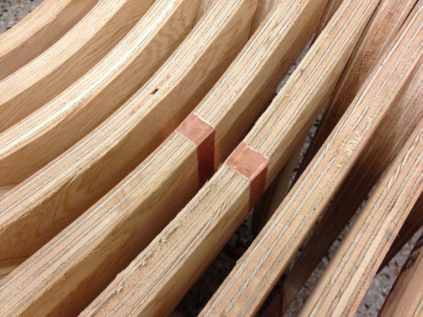
After some work, I extracted a lattice that could be cut on the shopbot and assembled with primarily friction and a bit of adhesive on for the beams.
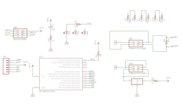
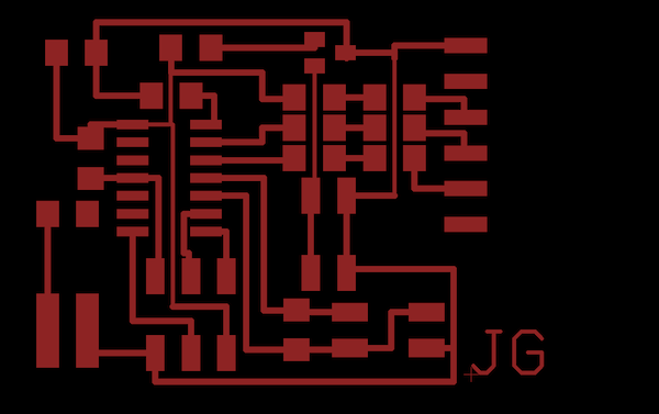
Electronics Design:
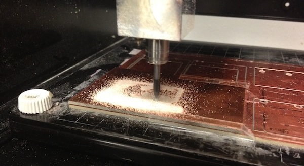
I had many ideas going into this one, probably too many and too many changes. But I started with the idea of these orbs suspended in the structure that glowed when someone approached or sat down. But realized that the milling and cast of these things might add too much work to the project.
So I simplified it to a network of 4 boards, one for each seat of the bench. And they would be connected with a long-range (~15ft) charlieplexed linear array of lights that would send impulses along the array to the other seat when one was activated. I realized, however, that my electronics design skills are not nearly intelligent as this scheme required. I then simplified it again to just one board and the linear array of LEDS. But realized soon again that I should start with something a bit easier, since coding and circuitry are certainly not my strength. In the end, I decided to go with a basic step-response sensor that triggered an LED. I told myself I would then build the complexity after I achieved this. Because it should be easy, right?
The Many Problems:
Structure:
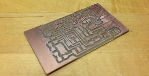
Well, this was disappointing. The part of the project I was most confident in was a bit of a disaster. I CNCed all the parts without any issues except for one; the drill bit came loose during a cut causing it to cut extremely deep. Apparently this was due to the taper of the collet (the bit holder) was dirty and thus more likely to move around.
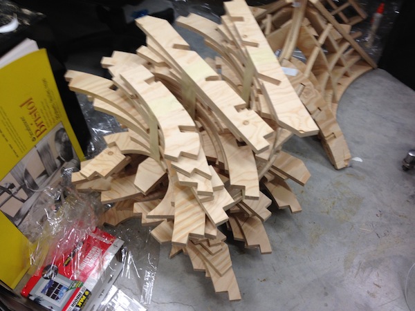
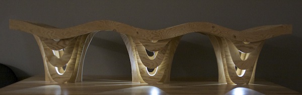
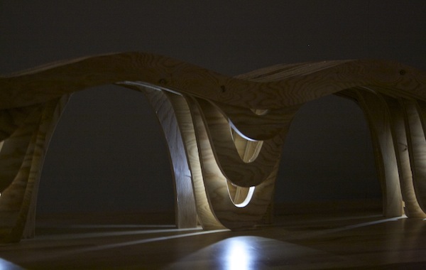
Then after assembling all the units without a hitch, I began to aggregate the units and found that they weren't aligning properly. After some investigation, I realized that it was most likely due to the small deformations of the edges since they weren't as accurately secured to the unit. In the end, the small differences culminated in a giant gap at the last connection (and lots of misalignments and smaller gaps throughout).
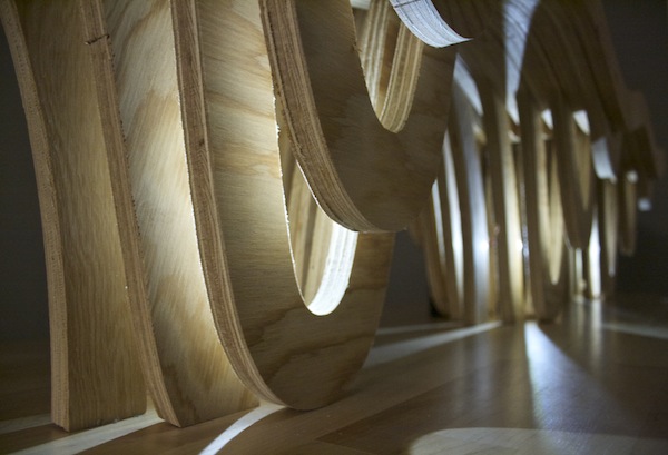
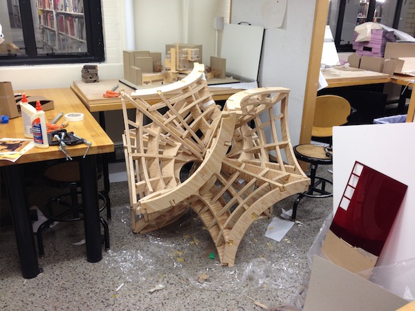
In addition, I quickly discovered that the unit I designed, while geometrically convenient and it made the fabrication simple, its aggregation did not at all lead to a structural form. And so the entirely of the form is somewhat delicate (not strong enough for a seat).
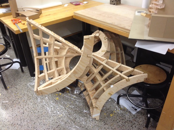
Moral of the story: there is probably a good reason why minimal surfaces haven't really been made at this scale—wood as a material is too rigid and doesn't forgive slight inaccuracies. Although not a complete success, I learned a lot about the limits of the lattice-method of fabrication and plywood as a material.
Electronics:
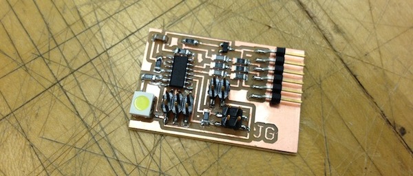
Combining the step response sensor with an LED is for most people a simple task. But it proved to be a challenge for me. I did learn a great deal doing it and managed to complete this part, though I was not able to expand upon it due to the amount of time it took me to complete it.
The following is a series of problems and their respective solutions:
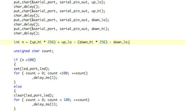
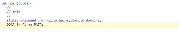
At least one of the step response pins should be an analog pin on the microcontroller… or else! Also, the step response code doesn't actually contain the number the python code displays, the python code calculates it. So to get that value in order to respond to it, you simply need to copy the equation over to the C code. [Thanks David!]
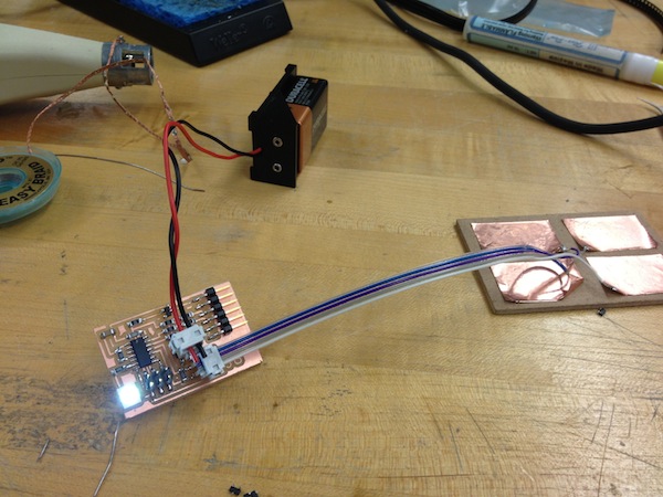
I had designed an FTDI and battery power supply for the board. I did this so I could more easily test the step response. What I didn't realize was that, if you connect via FTDI first and then try to use the battery, it won't work. By connecting the 5V output of the FTDI to the voltage regulator I was actually burning it. The solution, replace the voltage regulator in order to use the battery power. And if you need to use two power sources, then you'd need to place a diode in series with each source before the point where they all connect together. [Thanks Brian!]
Make sure you use the correct regulator; I used a 3.3V regulator instead of the 5V regulator by mistake and fried it repeatedly when I connected battery to the board. This cost several hours of reviewing my board and the connection and the design despite its simple solution. [Thanks Maria!]
Set the LED as an output. It's a simple line of code that I missed and it caused my LED to just be very dimly lit. This was also frustrating because I was working in bright rooms so I couldn't tell the LED was lit at all, so I assumed my code was wrong but I couldn't understand why. After a few hours, I noticed the light was just barely lit and realize the actual issue. [Thanks Moritz!]
Final Production:
Remember me?
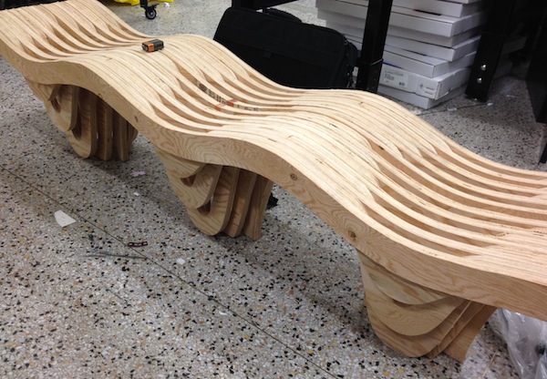
Since my Batwing was extremely delicate and it didn't seem like it could weather a journey to the Media Lab (or out of the studio doors), I decided to imbed my electronics into a previous project. The bench I made from the 'Big' assignment actually had a perfect house for of the electronics and it has a pretty nice visage when lit up.