
INPUT DEVICES: STEP RESPONSE TXRX
Building the Board:
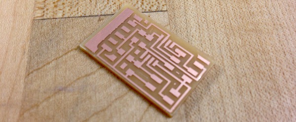
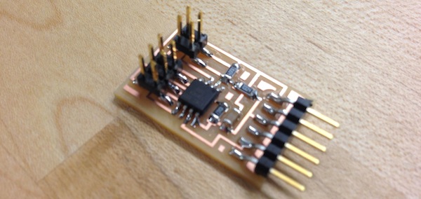
By now, milling and soldering the board and the components has become quite easy. And I had no problems doing this. I simply used the fab module and the provided pngs to cut the traces followed by the boundary of the Transmit-Receive Step Response board.
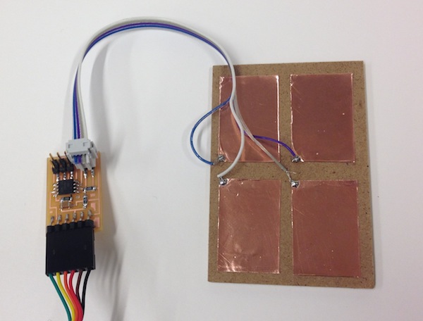
To build the sensor, I simply made a pad with four copper panels. I then soldered one wire from a rainbow wire to each of the copper panels. This raindbow ribbon was then attached directly to the four pin component.
Programming the Board:
Doing this, using the provided codes was simple, once shown to be my Moritz (thank you again!). Before that, I encountered some issues and now I have a couple tips to share as a result:
1. When trying to run the 'program-usbtiny' command, if you get 'error 1' before going and resoldering anything, just flip the rainbow ribbon connection on one of the boards.
2. If you can't run the make command, try downloading Xcode and CrossPack (for mac users)
3. For this sensor board, you are not using an external crystal and therefore you do not need to run the 'program-usbtiny-fuses' command (which was necessary for the embedded programming section). If you do make the fuses, you will have blocked yourself out of the microcontroller and need to replace it.
4. Once you program the board, you need to run the python script. To do this, Mortiz showed me the following commands:
sudo easy_install pyserial
python [enter python]
import Tkinker
^D [to exit python]
python hello.txrx.45.py /dev/tty.usbserial-FTFBDWY4
VIDEO
As you can see from the video, each of the panels has a different response (or non-response). Also, connections between two different panels also results in varied sensor readings, from very low to extremely high.