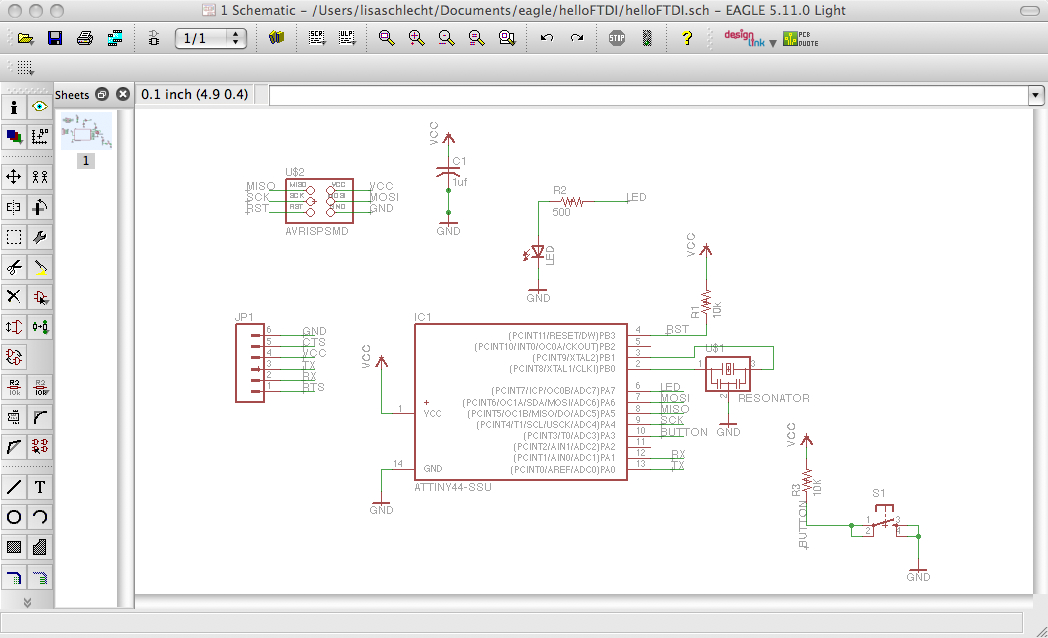
This week we built a slightly modified attiny44 microcontroller and practiced programming it. The first step was to create a schematic of the board, which was done using the program Eagle. The Freeware version allows you to design small boards for free, but remember to keep your designs in the (+x,+y) quadrant of the screen to avoid error messages. By default, Eagle includes a rather extensive part library, but you may want to download others according to the parts you're working with. To activate the libraries, click the grey dot next to the library name in the control panel (it should turn green when activated). Design in Eagle is split into two parts: the schematic view where you'll place and define the relationships between components, and the board view, where you adjust the physical layout of the board. While there is a toolbar on the left side of the screen, all the functions can be called faster using the command line (ex. "move" + enter). After adding components to the schematic, you'll need to add a net to connect the components. To reduce the complexity of your nets, you can indicate connected nets by naming both by the same name ("name"). Adding a label helps to clarify the schematic ("label").
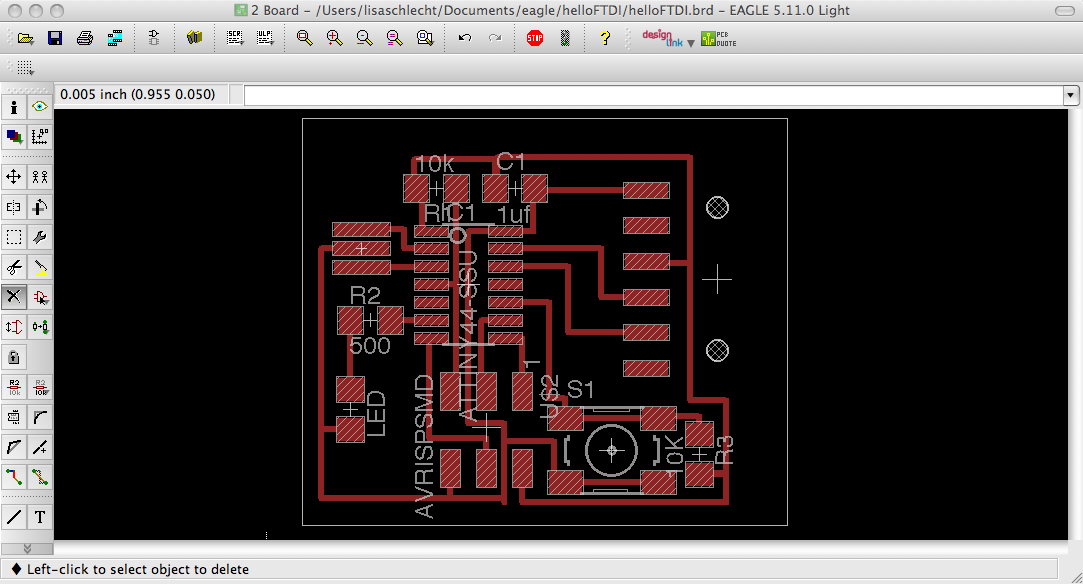
Once the relationships are defined, you can play around with their layout in the board view. The nets will show up as yellow lines, indicating where terminals need to be connected with a route ("route"). The "rats" command will check if there are any un-routed nets (which can sometimes be difficult to see). You should always do an "erc" (electronic rules check), "rats" (rats nest check) and "drc" (design rule check) to test your board before milling it. To export the traces as a .png, you want only the layer with the traces to be visible. Then go to file export -> image, and make sure to check "monochrome" and change the dpi to 1000.
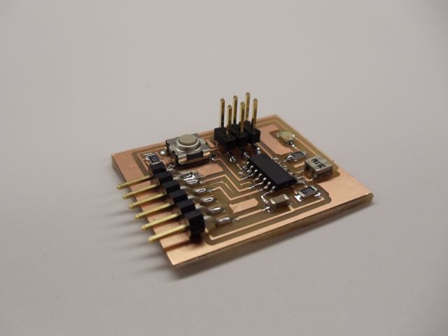
The next step was to mill out the traces and cut out the board using the Modela. For some reason, the board outline was not showing up when I uploaded to the .png file to the fab modules. It may have been because I used the grey dimension layer to generate the tool path, so I outlined the board with a thicker black line and exported a new image. This image did show up in the fab modules but it registered a different origin than it did for the traces, so it took some playing with setting the tool origin in order to board to come out right.


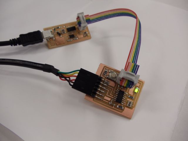
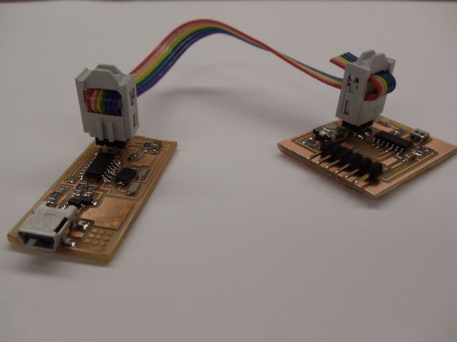
The next step was to stuff the board and program it using the FabISP we built a couple of weeks ago. I decided to initially test the board by using the Arduino environment and playing with the example programs. David Mellis provides some very clear tutorials. Don't forget to install the FTDI drivers for your operating system (a google search works). To upload programs into the microcontroller, you'll need to connect it to a USB port using the FTDI cable and to the FabISP with a ribbon cable. You'll also need another USB cable to connect the Fab ISP to power. I was able to upload and run programs incorporating the button and LED after switching the direction of the diode.
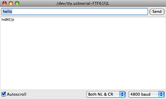
However, I was not very successful at getting the serial communicator to work, even when they were both set at the same baud rate. When I typed in a word or phrase, it would sometimes respond with random characters, other times it would respond with the same phrase but missing some characters.
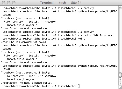
I also tried programming the board using the terminal and successfully made a hex file and programmed the board.
make -f hello.ftdi.44.echo.c.make
sudo make -f hello.ftdi.44.echo.c.make program-usbtiny-fuses
sudo make -f hello.ftdi.44.echo.c.make program-usbtiny
However, I got an error message when I tried running the program.
python term.py /dev/ttyUSB0 115200