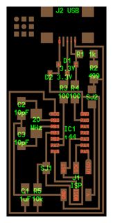
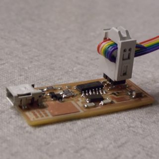
This week we constructed FabISPs which we will use to program microcontrollers. A schematic of the circuit and and a photo of the final programmer are shown below.
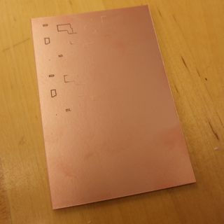
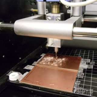
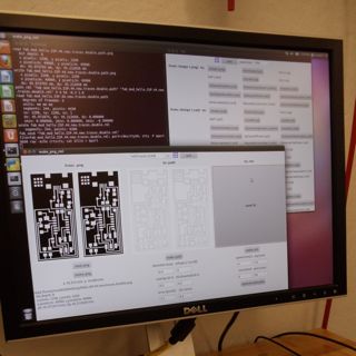
The first step was to mill out the traces on the board. This was done using the Modela in the Architecture Fab Lab, the fab modules, and .png files of the traces.
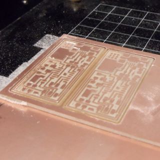
At first, I ran into issues obtaining traces of consistent depth. This was probably due to the fact that part of the sacrificial board had been cut into during earlier runs, resulting in an uneven surface. Fixing my board completely on top of a clean sacrificial board solved this problem. The modella tutorial says to not to overtighten the bit but I found that I needed to tighten the drillbit beyond snug so that it wouldn't slip up into the chuck when force was applied. After cutting out the traces with the 1/64" bit I switched to the 1/32" bit to cut out the boards.