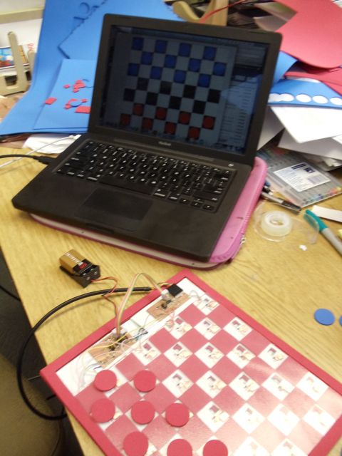
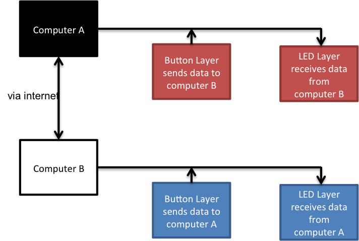
It's the end of semester, and it's time to put together almost everything I've learned over the past week into a final project. The first step was to make a board that interfaces with a computer. The board I designed has two layers, an output layer with an array of LEDs, and an input layer on top with touch sensors. I modified the sample bus code in order to be able to have serial communication between both boards and the computer with only one FTDI cable. A schematic of my first goal is shown below.

I decided to focus most of my effort on the design of the circuits and programming before fabricating anything. This allowed me to make modifications to the circuit design as programming issues came up and to incorporate feedback from others, without requiring building and soldering a whole new board. I started out trying to model the circuit in Eagle, but found that the free version does not allow you to design boards larger than a few inches. I ended up using Adobe illustrator to model the traces, which I found was better for my purposes because it is much easier to drag and resize graphics than to rip up and re-route traces in Eagle. In my opinion, Eagle is good for smaller circuits that you haven't made before because it keeps track of which components should be connected, but Illustrator is better for modifying and expanding on existing designs.
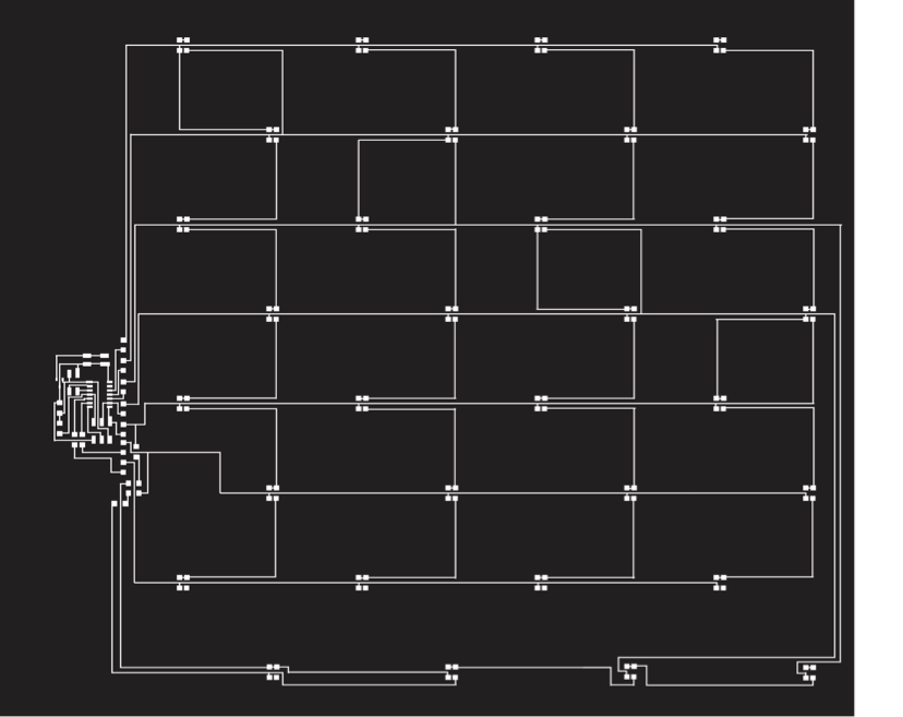
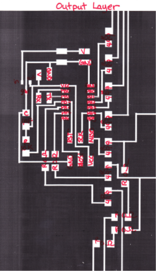
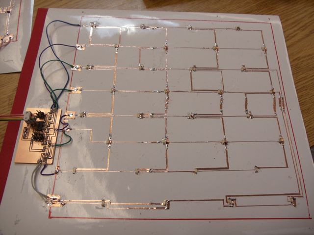
Output LayerFirst I modeled the LED layer, expanding on the example LED array to include 32 LEDS, which required 7 pins. Since my board has 4 columns and 8 rows, I made a 4 x 7 charlieplexed array, and then added the 4 extra LEDS to a 5th column, which allowed me to confirm that they were routed correctly. Then I moved the LEDS to the 8th row and made sure the routes connected to the correct rows. The final LED circuit is shown below, as well as a close-up with annotations on the microcontroller portion. I added a four pin header to connect it to the input layer.
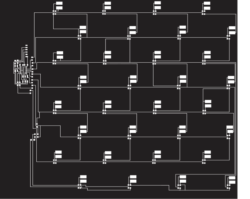
For the input layer, I decided to make an array of homemade touch switches. This layer will be covered with a layer of foam with cutouts above the switch pads. The bottom of top layer will also have a copper contact pad. Therefore, when the square is pressed down the circuit will be completed, acting as a button. A matrix of buttons would require 12 pins, but by taking advantage of charlieplexing again, I can make 32 buttons with 7 pins. I used the same charlieplexed array from the output layer, moved the diodes over so they wouldn't cover the LEDs below, and adding the touch switches in series with the diode. The circuit and a close-up are shown below.
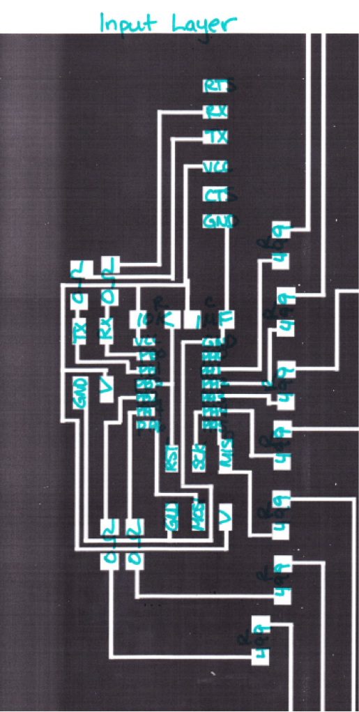
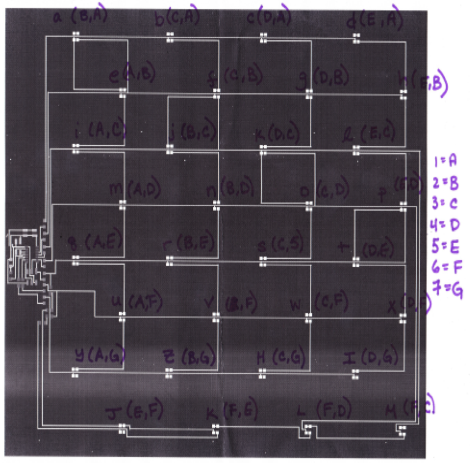
To code the board, I started with example bus code and incorporated the LED array code so that the output would be dependent on serial input from the computer. Each square is given a character to identify it and its input and output pins (as shown in the picture below), and these characters are what will be sent to the output layer and from the input layer. To get input from the button array, the board needs to cycle through testing each square until it finds a completed circuit. I'm doing this by setting one pin as the input and clearing the output pin, then reading the input pin and if it is 0, sending the character for the corresponding square to the computer.
I was originally aiming to make two boards, but given the time and components required to make a second board, my fall back is to make only one and to have a online user interface that the other person uses. Since the boards are identical, I think prototyping one would be a successful prooof of concept. I think that having only one physical board may be a more interesting project anyway because it incorporates more of what I have learned over the semester, and the design may also be better for families where one member has to travel often, and therefore may only have a laptop on hand.
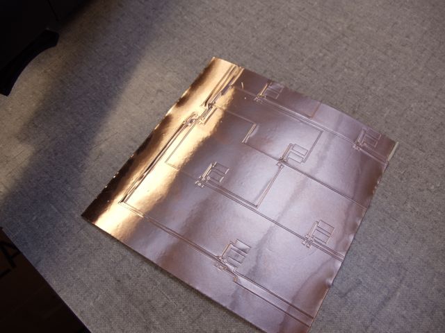
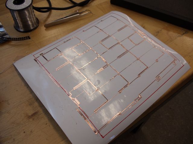
I changed the design a little so that Tx would be connected to PB1 and Rx to PB2. Then I started vinyl cutting. I wouldn't say that vinyl cutting is rapid prototyping, then entire process of finding the right settings, cutting everything then transferring and weeding it took about two full days of work. I did learn some tips that helped me with my particular circuit. Since my circuit was so big and has two layers, there was no way around using the vinyl cutter. However, the copper tape in the Arch Shop was only 6" wide, so I ended up needing to cut up my design into fourths to be able to cut each part with minimal problems. If you're cutting delicate parts like circuits, it seems to work better to have a relatively small area, because it minimizes air bubbles and bowing that you'll get from a larger piece of copper tape (since it's wound around a tube). I also found that low speeds and relatively low forces of around 55 g worked better. I had a lot of trouble cutting and weeding the first version of the circuit, so I went back to Illustrator and made as many of the traces as possible thicker. This made cutting go a lot more smoothly, and weeding was easier as well. I had to do some repairs on the weeded surface with strips of copper tape and solder to make sure that the four parts were connected.
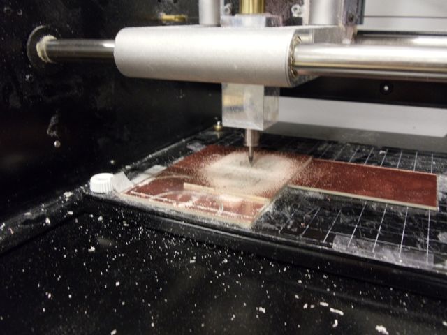
I tried vinyl cutting the microcontroller portions of each layer but it was difficult to cut the delicate parts without ripping too much, so I decided to mill out the boards on the Modela. The thicker board would also standup better to repeated plugging and unplugging, or forces on the cables. Milling the boards went relatively smoothly.
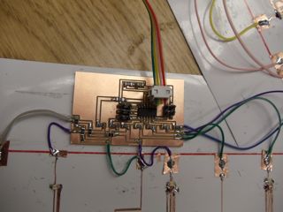
I had two boards with 32 charlieplexed components so stuffing took a while. On the LED board I used blue surface mount LEDs, and on the button layer I used 200 mA diodes. Then, to avoid using a lot of zero ohm resistors, and since I didn't want to add an epoxy layer because it would make the lower layer harder to debug later, I laid a bead of hot glue over the trace and then put a small bridge of copper tape across and soldered both ends. For the boards, I ended up soldering wires from the traces to contact pads for each row. Using wires worked well for areas where I would have needed a zero ohm resistor to accomodate overlaping traces.
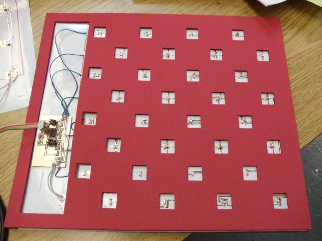
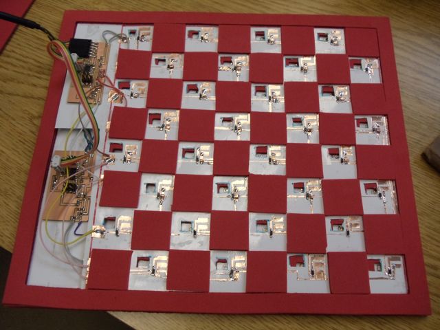
For the foam casing I used Illustrator to make the designs and then cut out the pieces on a laser cutter. The foam layer provides some color and a nice tactile quality to the board, and it is just the right thickness and stiffness for the homemade touch sensors. Then I added a clear plastic sheet on top and adhered the copper contact pads that would complete the button circuit.
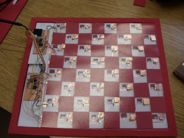
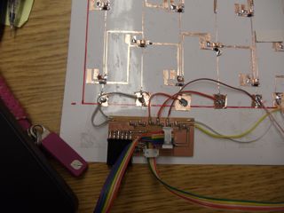
Unfortunately, the board doesn't work yet. I was able to successfully upload the programs, but the board does not respond as expected. This is most likely due to a short circuit or break somewhere in one of the layers but I'll keep debugging. The program was coded in C and Python. Below is a picture of how it would look in action. I learned a lot from this project, and I had no idea how to make something like this before this class. I'm looking forward to tackling more projects!