
After Nadya's workshop this week I had grand ambitions of networking some stepper motors for my final project. This seemed achievable given the documentation of the MTM machine and stepper motor controller boards. I set out to make a few not knowing what I was getting into...
I'll mention all the things that went wrong this week since there are far more of them than the things that went right. The modela machines both at CBA and at the arch shop seemed problematic. This may be due to the high usage and wear on the milling bits. The traces I milled were very sloppy and hairy. Unfortunately it did not matter because the pngs I used to cut the files was scaled to an unusable size. I cut a new one at actual size to compare but stuffing the board became impossible. The electronic components have been out of stock the entire week so the six components on the board were the only ones I could find. I ordered a stepper motor controller chip to finish the board but its will not arrive for a few days.
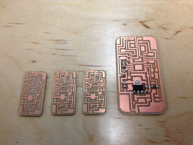
I decided to try to make some of Andy's "anduino" chips that are shield compatible. These will be potentially useful if I make the triple motor controller shield from the MTM machine to run my final project. It took several days to make these since as Andy would admit, they are a work in progress. Andy was kind enough to make changes to the chip as I ran into problems, but we eventually made a few good prototypes.

I worked on a few different connectors to interface all the boards I was making as well as a microphone chip that I was interested in using for my final project as well. Until Saturday I could not finish the mic board because I couldn't find any FTDI connectors. The electronic component supply was minimal this week which made it difficult to finish multiple boards for a network.
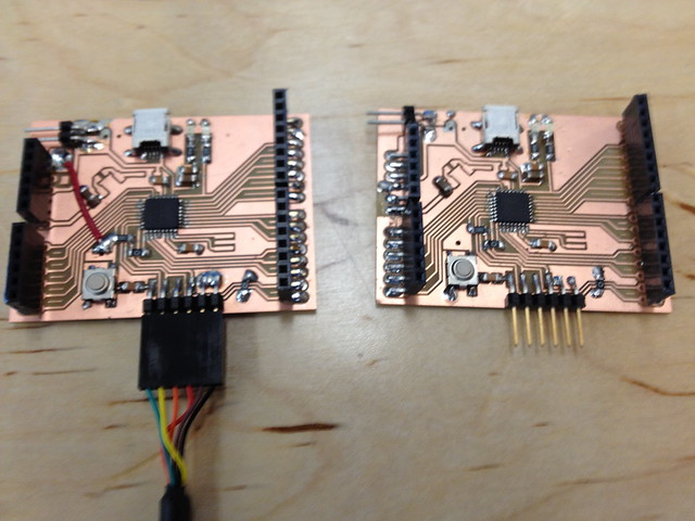
I eventually turned to the bus example to make a network or chip. As was common this week, I made a mistake while milling. I accidental milled three bridge boards instead of a bridge and two nodes. The boards are almost the same except the bridge has an added FTDI connection. I had to make these at the arch shop which had a few more supplies.
Unfortunately they did not have 2x2 isp connectors to make the network connection. I had to improvise a connection by adding another FTDI connector, piggy-backing the first so multiple wires could be connected.
Each chip was programmed by itself with separate node identifier keys. This allows a standard signal to be read by each node but interpreted depending on the identifier. For example a signal is sent out that says that node one should blink its light. every node will read this signal but only the node that has been identified as node one should respond.
I choose to interface the chips with Firefly/Arduino. I was a new work flow for me that I was interested in exploring. I was successful at writing data to the network via the serial port but things were not exactly right. All the boards blinked regardless of with number was given, even if that number was not programmed to any chip. Since I was following Neil's programming guide, I can only assume that the problem lies with the way I setup the Firefly/Arduino interface. I am yet to understand the problem.