http://www.playatech.com/depts/03Bare%20Necessities/09Gear%20Gizmo/plans/Gear%20Gizmo%20Assy.pdf and make requisite donation
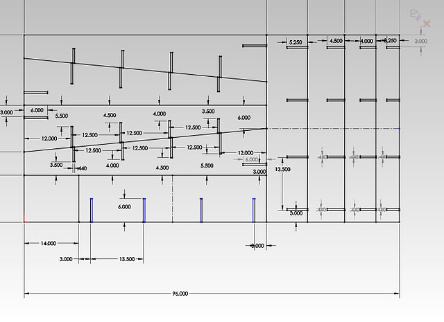
Yes, it’s all one giant sketch. Terrible practice, I know.
I had to create this file several times because I was slack on adding Dimensions, instead just placing points where I wanted them (specifying when I created the point without going back with a “smart dimesions” tool).
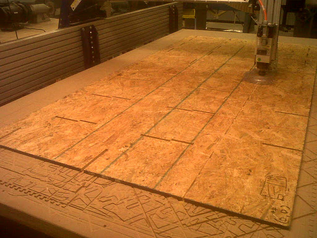
This is where I learned that generally, you don’t make designs that us ALL of the stock on the shopbot. You really want a margin
However, being silly, I thought it wouldn’t hurt to go ahead and try anyway (sorry everyone who politely tried to make things easier for me). I figured that I could cut without detaching any parts, score the remaining lines, and then finish things up on the bandsaw / using a jigsaw.
I thus put 9 holes where I knew there was a wide margin of error where the shopbot tool should not come anywhere near and carefully zero’d all the axis to be as accurate as possible. Yay tape measure + sharpie!
I minimized the amount of measuring I needed to do by picking each x with 3 different y-values, instead of my haphazard 9 values with all different x’s and y’s originally.
Interestingly, I had some major issues getting closed vectors in partworks. I used “Mirror” in solidworks to create parts of my design. The original parts recognized themselves as connected vectors. The mirrored lines didn’t. I ended up deleting the mirrored portions in partworks and copy-pasting the lines I needed.
To do this without messing up the dimensions, I took advantage of the fact that Partworks copy-pastes in place. I would copy the ones I wanted (the “closed-vectored” lines), paste, then hit the up arrow key to move the copied lines over the solidworks lines-which-won’t-close/allow-me-to-fillet, zooming in to make sure the copy was exactly over the solidworks lines since it doesn’t seem to snap. Then I would hit Ctrl-C again. Then I would hit delete, then delete the solidworks lines as well. Finally I would hit Ctrl-P and the lines would be pasted in the correct place.
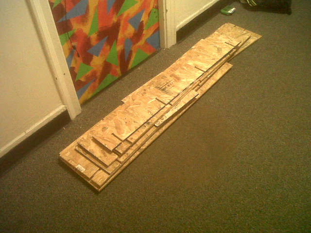
Material used: One 4’x8’ OSB sheet, 7/16’’, provided by the class.
http://www.homedepot.com/Lumber-Composites-Plywood-Sheathing-Subfloor-Oriented-Strand-Board-OSB/h_d1/N-bqpqZ5yc1v/R-100091344/h_d2/ProductDisplay?langId=-1&storeId=10051&catalogId=10053
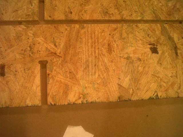
I measured ~0.45’’ thickness and cut to 0.46’’ depth. This worked out well as the board was not perfectly flat in some places for the first cut.
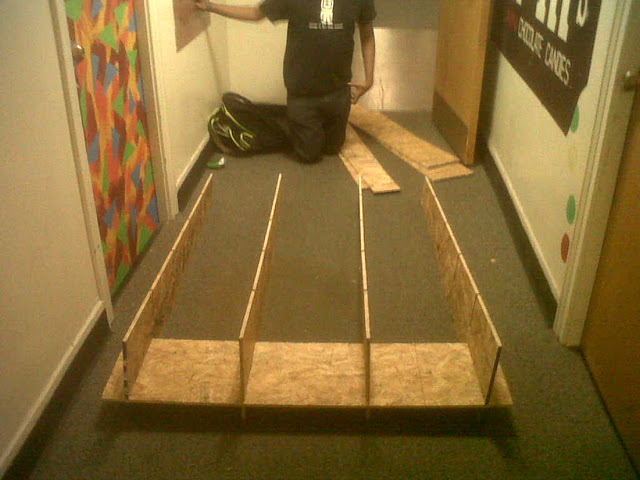
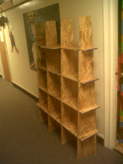
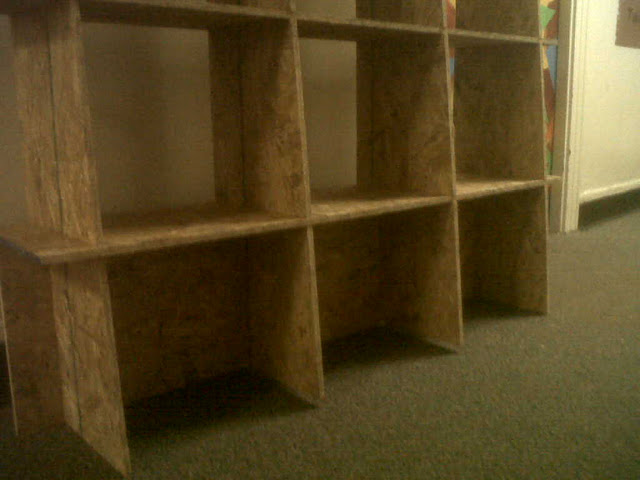
In the design, I didn’t compensate for the width of the tool. As a result, there were minor differences in the “identical parts” but the slack in the design allowed me to assemble it anyway. When I put it together, I realized two pieces were longer than the other two and made sure to put them on the outside. You can see the two pieces hovering @ ⅛’’ off the floor (half the tool radius) below.
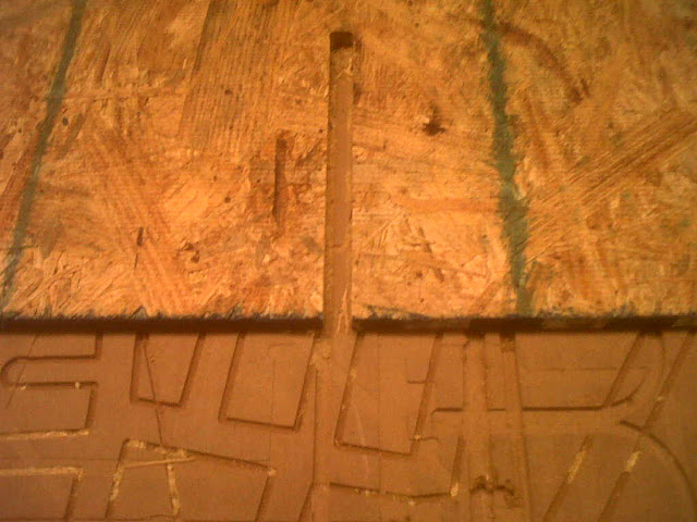
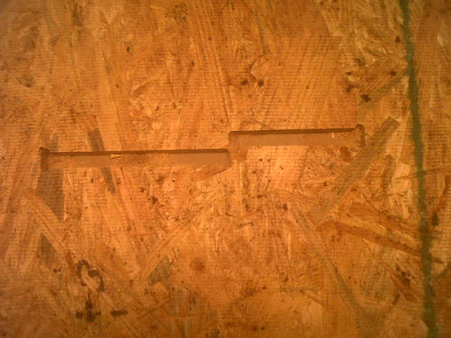
On some parts, I put a t-bone fillet for a ⅛’’ (see left pic below) instead of a ¼’’ tool (right pic below). Later, I couldn’t fix this because I couldn’t delete old fillets. This worked out okay due to the leeway in the design.