I would like to thank all the people who spent the time to help mein the last couple weeks:
David Costanza, Alan Cramer, Andrew "Ozz" Oswald, Peter Schmitt, Daniel Rosenberg, Carig Bony, Nancy Ouyang
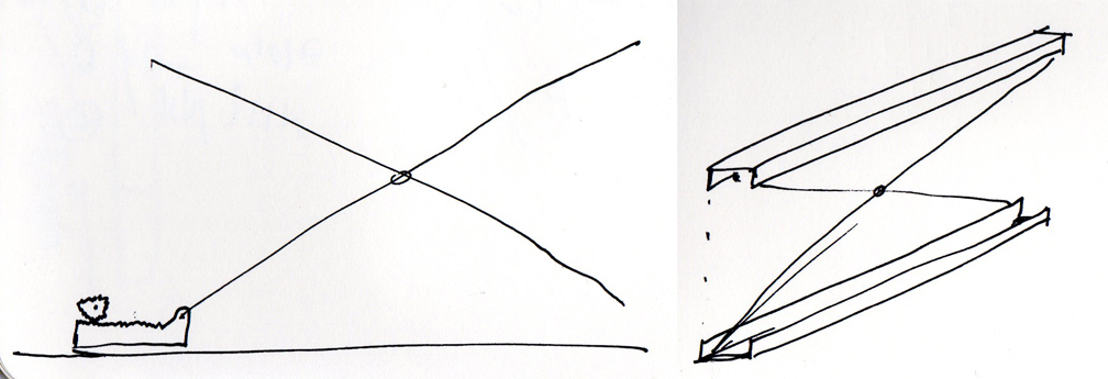
Two U shape beams made out of Plywood erected by two 1” diameter conduits
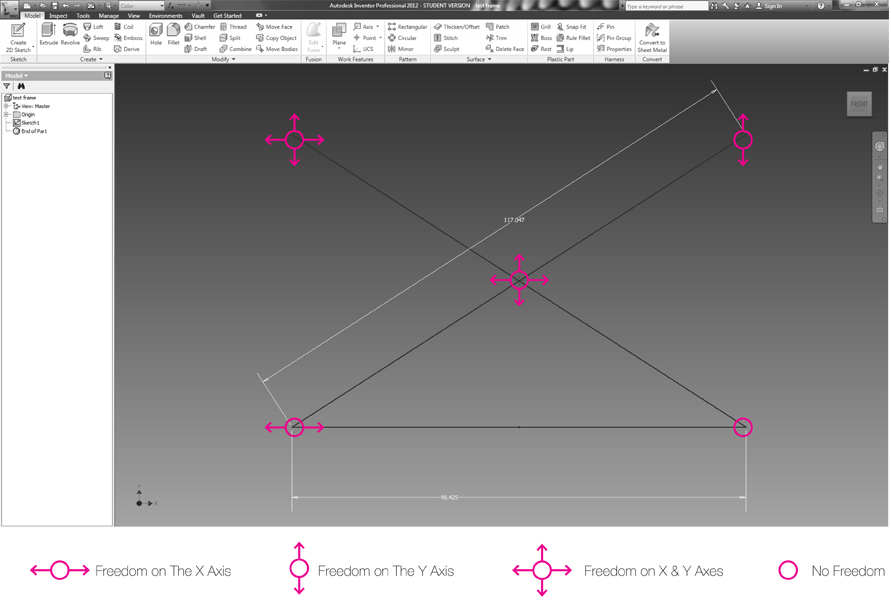
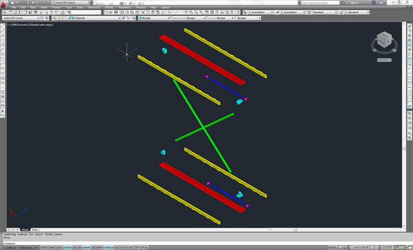
With the help of Adam Cramer We created a model in Inventor order to understand what would be the degree of freedom of each pivot.
With the help of David Costanza and Andrew "Ozz" Oswald I started to learn what kind of part I needed:

In order to get a smoother motion there is a need to use an Acme lead screw as opposed to a regular screw. The length of Acme screw is 3 ft.

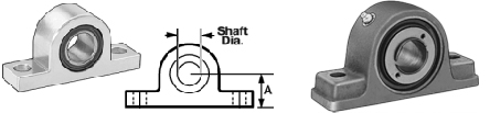
Pillow Bearing holds the Acme lead screw.
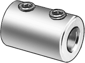
My first assumption was to connect the Acme screw to the motor with Shaft Couplings.
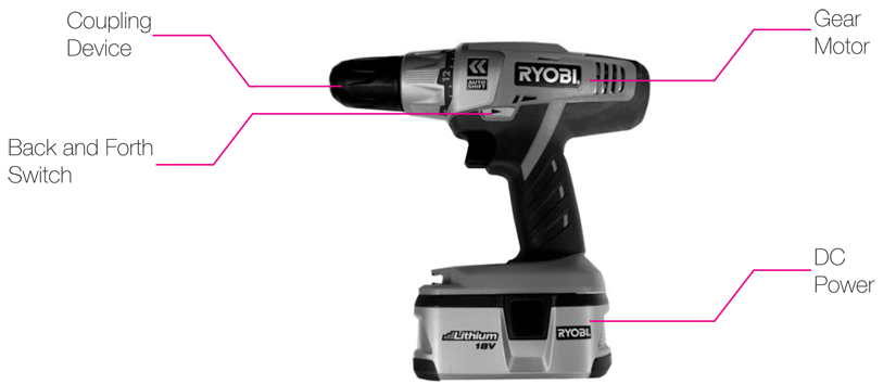
With the help of Peter Schmitt I was able to define the properties of the motor that I need to erect the Sukkah. I need only two motor one on each side which will have the following properties:
In general the cutting went smoothly.
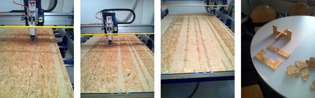
The only advice that I can give is when you cut big pieces you should wait that the machine will mark the first round of the piece and screw it in strategic points to the machine’s board in order to prevent the plywood from vibrating and by doing so the mill might break or cut the piece in the wrong place.
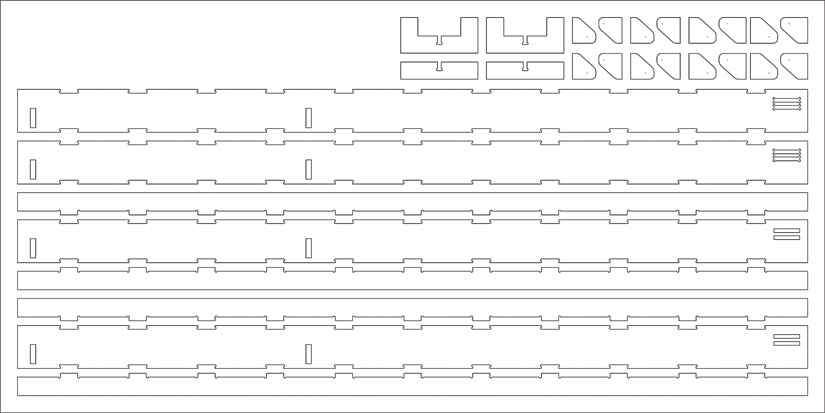
Two sluts were milled on each panel in order to insert the brackets and allow a better adherent.
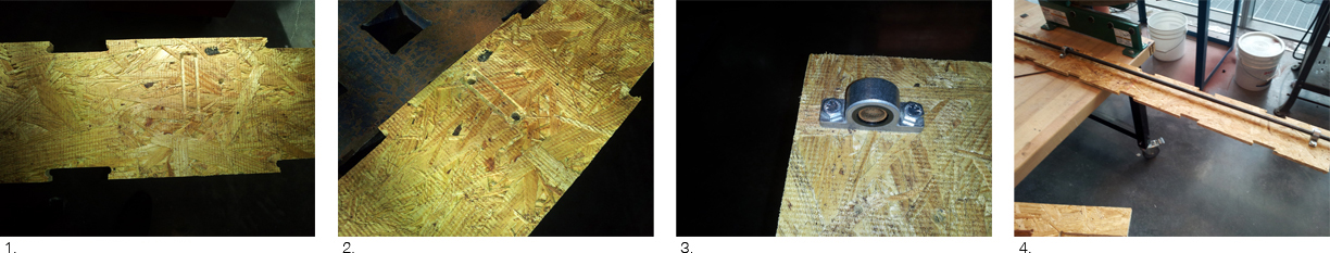
1. The location of the pillow bearings were mark in advance in the milling phase.
2. Two ¼”holes were drilled in the edge of each mark.
3. The pillow bearings were screwed to the plywood.
4. The ½” acme lead screw was pushed through the pillow bearings.
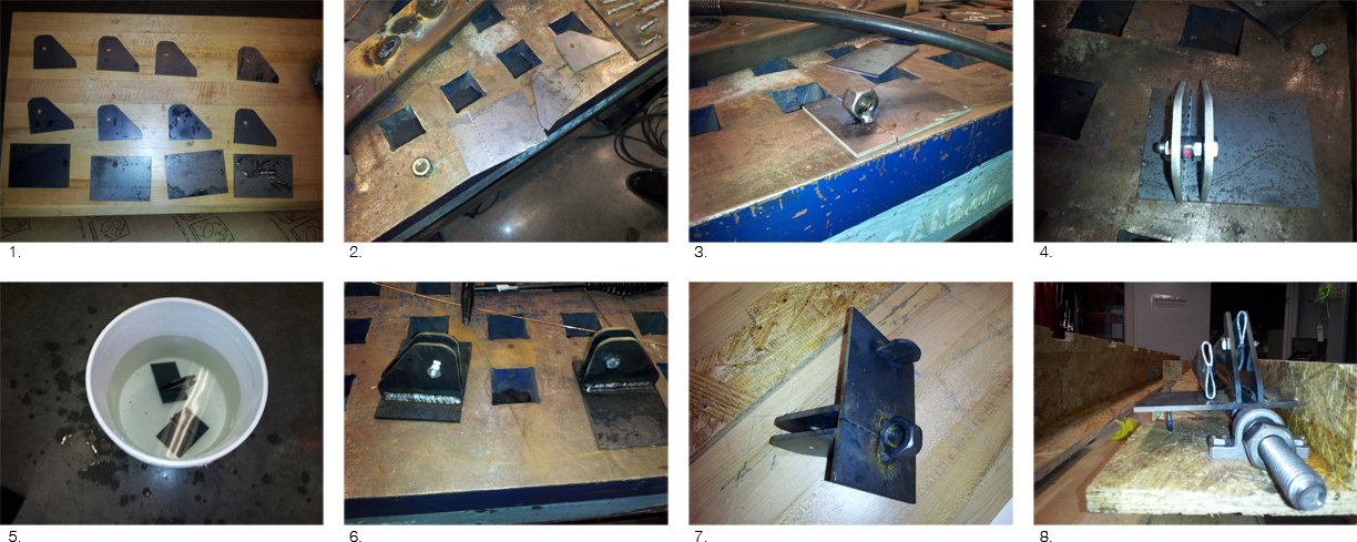
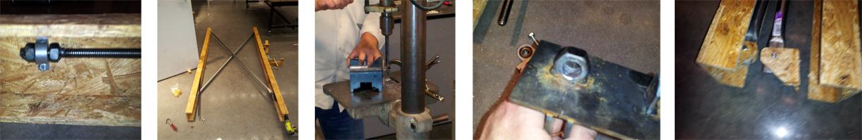
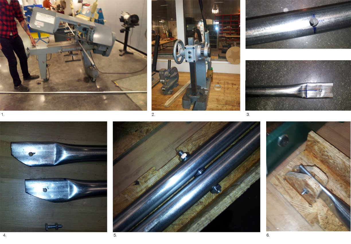
1.The pieces were cut with a water jet.
2. Marking the location of the brackets and the acme nut on the steel plates.
3. The acme nut welded to the steel plate.
4. Affixing the position of the steel bracket using nuts.
5. Cooling the steel brackets after the welding.
6. The result
7. Adding steel stand to balance the steel brackets and preventing them to flip.

1. Gluing the first stringer.
2. Detail
3. Placing the conduits.
4. Putting the beams on each other.
5. Gluing the second stringer.
6. Plywood brackets
7. Steel brackets
8. Result
Problems