![]()
![]()
- 1. project description
- 2. milling FabISP
- 3. stuffing FabISP
This week we had two different sections. The first was about how to mill our boards using the MDX20 Roland Modela and the second one about how to solder the components and program our boards.
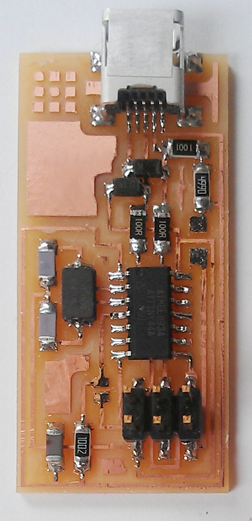
This week I learned how to make the FabISP in system programmer, with which you can program microcontrollers on other boards with a USB cable and a 6-pin IDC to 6-pin IDC cable. The board design, the traces and the components had been provided to us. The task was to mill the board using the MDX20 Roland Modela, to solder the right components and to program it.
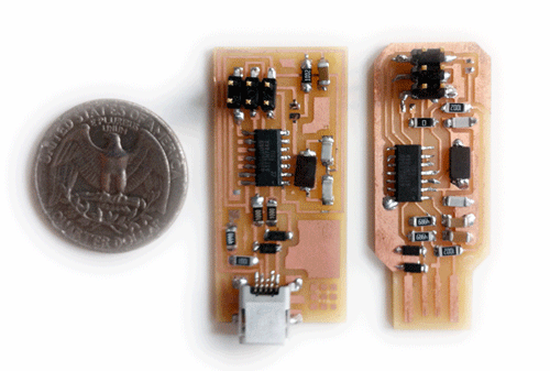
I tried two versions of the board and I used the first board to program the second. The board on the left below is the one which had been provided in class and the one on the right alternative version developed by Andy Bardagjy who got rid of the USB cable connector. In the "milling FabISP" and "stuffing FabISP" tabs of this section you can find the documentation of the steps that I followed to make my boards along with tips and lessons learned.
Figure 1: The two versions of the FabISP in system programmer that I made this week
How to use the MDX20 Roland Modela to mill your board
You can find great tutorials for that here. However, following the spirit of the greek saying that "Repetition is the mother of knowledge" I am adding below the notes that I kept during the miling tutorial that Brian and David gave us at the CBA shop, as well as some personal experiences, do's and dont's for each step.
How to place the board in the Modela plate:
1. Always put another layer (a board you are not going to use) under the board that you want to mill.
2. Take a clean new board (FR1, copper thickness 0.04mm) and fix it on the substrate with a double sided tape. Make sure that there are no fingerprints (they make soldering difficult) on it and that it is completely flat. Note that the board can be washed with water and soap so as to clean the surface.
Things to keep in mind:
> Always mill on FR1 and not on FR4 boards. FR4s contain fiberglass and they often cause the end-mill to break.
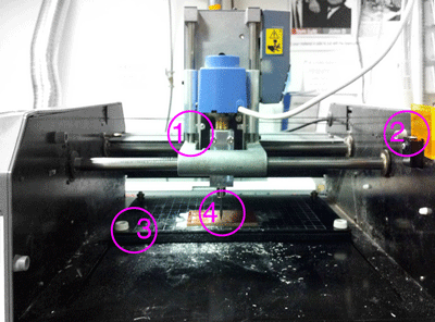
> The origin (0,0) point of the Modela is at the bottom left corner of the plate (see #3 in Figure 1). You will need to specify the starting position of the end-mill later on so it is useful to be able to easily situate the edges of the board within a coordinate system. The gridded Modela plate is very useful for this process. Remember that each grid module corresponds to about 1cm.
> The Modela is supposed to have a lid, which in this case is substitited by the orange piece of plexi (see #2 in Figure 1). If you take it off the machine will stop. The absence of the lid makes everyone's lives easier but makes wearing protective glasses necessary while the machine is operating for the unfortunate event of the breaking of the end-mill tip.
Figure 1: The MDX20 Roland Modela at the CBA shop
How to put the end-mill in the Modela:
1. Select the right end-mill. In order to etch your board you use the 1/64" end-mill (see #4 in Figure 1), whereas in order to cut the board you use the 1/32th" end-mill.
2. Press the View button on the Modela. This moves the plate inwards.
3. Use the Up button to make enough space to insert the end-mill. Insert the end-mill so that only the tip is visible and slightly tighten it.
4. Use the Down button to lower the tip. A rule of thumb is that you should stop lowering the tip when there is almost one finger distance left for it to not be able to go further down (see #1 in Figure 1).How to zero the end-mill:
1. Run the fab module for Roland Modela. In the interface you can see the diameter of the tool, the number of offsets (this shows how many passes you have for each trace) and the depth of mill (0.1 is enough to cut the copper)
2. Count the number of grids from the top left corner of the Modela plate to the top left corner of the board. Keeping in mind that each grid is 1cm you can specify the coordinates of that point. Write them down!
3. Using the same way to calculate coordinates move the end-mill to the center of the board. This is where you should always zero your end-mill because it is often the case that the board edges stick out a little.
4. Loosen the screw
5. Put tip down carefully until it touches the board surface and tap it a little -carefully again!
Tighten the first screw a little bit, then fully tighten the other screw and go back and tighten the first one.
Attention: If you do not tighten well enough then the end-mill can fall off and break while it is milling. This will mean that a.you will have wasted an end-mill; b.you will have wasted a board; c.you will have wasted valuable time.
It happened to me: In one of the iterations that I did, the end-mill could not be tightened well enough because the Modela had accidentally two instead of one end screws, causing the small crisis I just described.
6. Move the tip back to lower left edge of the board.How to send the file:
1. Load the correct file and select the correct setting corresponding to what you want to do (mill traces or cut board).
2. Make sure you have set the correct values in the fab module. In my first iteration I tried 4mm/sec but the board came out rough. 3.5 mm/sec was slightly slower but gave a much cleaner result.
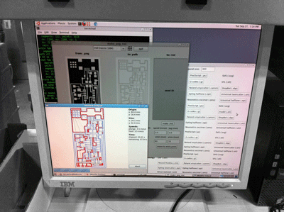
3. Make the rml file (make_png_rml)
4. Send it!
Figure 2: make_png_rml GUI
After you have etched and cut your board:
1. Remove it from the board with a spatula
2. Make sure that the surface is clean and the copper edges of the traces are smooth. Sometimes when the etching goes roughly it leaves copper "hairs" on the board which can even short circuit it if you do not properly remove them. You can do this by uniformly scratching the board surface with a spatula.
In this section I will describe the process that I followed in order to stuff my FabISP board. I will first document some useful tips which helped me to successfully go through my first ever soldering experience and then I will go through the steps that I followed to make Andy Bardagjy's board explaining a few basic things about the components.
Soldering tips
Soldering requires precision and a steady hand, both of which come with practice and experience. However, even if someone is an absolute beginner (like myself) there are a few tips which can help. In my case Nadya Peek's handout and Bryan and David's advice proved really useful.the technique I used:
1. Put a small drop of solder on the board
2. Hold the component with a tweezer on the solder.
3. Heat the solder with the iron and connect it to the component
4. Solder the other side of the componentAnother good way to do it is to use flux which prevents the solder from extending beyond the copper paths and solder the ends of the component by holding it down with a tweezer.
Some things to keep in mind:
> Keep soldering iron tip clean.
> Make sure you do not "overwork" the solder. It should be smooth and shiny at all times. Rough surfaces or dark color are bad signs.
> Careful with solder overflows. The solder can pass to adjacent paths and short circuit the board
> (Almost) Everything can be undone. There is a great tutorial for soldering and unsoldering by Carolina here. A technique that eventually worked for me when I needed to unsolder small components was to heat the solder with the iron and solder wick and then lift the component with a tweezer.
Components
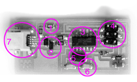
1. Resistors:
> direction free
> measured in Ohms. They are read as follows: [three first digits] x [10 in the power of last digit]. For example 1001 is [100]*10^1 which is 1KΩ2. Zener Diode:
> direction does matter
> the side with the thin line is the cathode
> diodes are measures in Volts (V)3. Microcontroller:
> Direction does matter
> make sure that the round dot at the edge of the microcontroller is in pin14. AVRISP:
> the rounded pad corresponds to pin1 - keep that in mind when connecting it through 6-pin IDC to 6-pin IDC cable to the AVRISP of another board.5. Crystal:
> direction free6. Capacitor:
> direction free for ceramic capacitors
> measured in Farads (most commonly microfarads μF)7. USB connector:
> Difficult to solder but luckily we do not need it any more. See the USB connector-free board at "project description"Programming the board
I programmed my second board using the first one. I had to download firmware.zip from here and to run the following commands:
make clean
make hex
(sudo) make fuse
(sudo) make program
Then after desoldering the two solder jumpers and the board was ready to use. It was great to see that Valentin Heun found a way to skip that step two!