![]()
![]()
- 1. project description
- 2. boatyard visit with 4.116
1.1. General:
This week I made molds producing thin shells. My inspiration for this is the technique of hollow lost-wax casting which was used in ancient Greece for the production of bronze statues. This technique comprises the model of the object made in clay, then covered with wax which is in turn covered with another layer of clay. When the model is baked in high temperature the wax between the two clay surfaces melts leaving a hollow space between them, where the metal is subsequently cast. This concept of casting-in-between was the point of departure of my work this week.Take 1: sea urchin skeleton lanterns
Figure 1: the Lanterns1.1.1. Concept & Modelling:
The idea of this project is to make a hollow ribbed sphere with a light source inside. Although the resemblance is not direct I assume that I was inspired from the sea urchin skeletons that I collect in my summers in Greece.
The two main goals were:
1. to find a way to produce a thin shell by filling the space between two molds (as in the technique I formerly described) and
2. to deal with the obvious undercut problem.
In order to do that I made the ribbed sphere from two hemispheres put together leaving a thin slot in the middle. Each of the hemispheres is cast between two offseted surfaces, a positive and a negative. The cast part is therefore the void between the exterior and the interior part of the sphere.
I used Rhino OSX to 3D model the hemisphere. The way that the form is produced is through a radial array of a surface lofted between a circle and an ellipse rotated 18 degrees in relation to the circle. The large axis of the ellipse equals the diameter of the circle and small axis is 75% of this diameter.
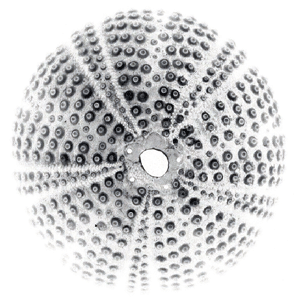
Figure 2: A sea urchin skeleton
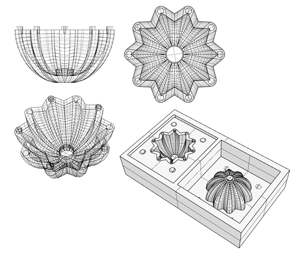
Figure 3: the 3d model of the ribbed hemisphere and the 3d model of its mold
The main challenge in terms of design was how to make sure that the detail I was designing would be realizble with the diameter of the bit that I was using (1/8"). For example, my initial ambition was to create positive and negative tabs in the thickness of the shell which would allow me to rotate put the two hemispheres together by simply rotating them. It did not work; in the milling process I only managed to get the extruded tabs. In order to be able to realize the idea of the tabs with an 1/8" bit I had to model the shell rather thick, which ruled out the idea of a potentially translucent shell. Definitely something I want to try soon.1.1.2. Milling the wax mold:
I used the PRSalpha 120-60 ShopBot at the CBA shop to mill the machinable wax. Josh showed me how to use RhinoCAM to make the toolpaths for the ShopBot. I used a 1/8" flat bit with 10000 spindle speed, 200 feed rate and 75 plunge rate, with 40% tool offset. The milling took approximately 60 minutes without any problems.
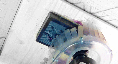
Figure 4: Milling the machinable wax at the CBA Shopnot
1.1.3. Making the silicone mold:
I used oomoo 25 to make the two silicone rubber molds of the ribbed sphere. The product information sheet gave very straightforward instructions in terms of the mixing analogies and order. The part of the process that was challenging was to make sure that there were no air bubbles trapped in the silicone, which can really compromise the quality of the rubber mold. A way to do this is to pour the oomoo on the wax mold with a very thin stream and to gently shake / hit the mold with the liquid silicone on the table after finishing the pouring. This brings trapped air bubbles in the mass of the silicone to the surface, which then makes it very easy to break. Oomoo 25 normally takes 75 minutes to dry but this can vary according to slight differences in the mixing analogies. A rule of thumb would be to demold the silicone when its surface is not sticky anymore.

Figure 5: Making the silicone rubber molds
1.1.4. Casting:
For casting I used Drystone.
In my first casting I attempted to pour the Drystone from the pouring hole at the top of the mold. However, the diameter of the hole was not letting enough material to go in, resulting in a non uniform cast part which broke when I tried to unmold it.
Figure 6: Casting the Drystone in the Silicone Rubber Molds
The technique that I finally used was to:
1. turn the mold upside down;
2. seal the pouring hole with tape;
3. pour drystone in the negative mold filling it half way;
4. place the positive mold on top of the negative mold (some drystone overflowed)
5. turn the mold upside down;
6. unseal the pouring hole;
7. use medicine dispenser to add extra drystone from the pouring whole until I make sure that the cavity between the two molds is full.
Figure 7: The molds and cast parts
Figure 8: The cast parts
1.1.5. Lanterns:
In order to make the lanterns (see figure 1) I drilled the top of the cast piece with a 1/4" bit and used an LED with a 3V battery as a light source.
Figure 9: The Lantern kit; a 3V battery, an LED and the cast part drilled at the top
1.1.6. Casting with translucent material:
This morning I tried casting with a 5 minute drying epoxy in order to achieve transparency. The biggest problem are the air bubbles, which is aggravated by the fast drying nature of the epoxy. The result is quite suggestive and I would like to experiment more with it.
Figure 10: Casting with epoxy
Take 2: a knife handle with an embedded accelerometer
Figure 11: A knife handle with with an embedded acceleroneter
1.2.1. Concept:
This idea is along the lines of my prospective final project, which comprises a knife and cutting board set acting as a sensor and display respectively. This week I tried to create the molds for the knife handle. Although the Drystone was far from an ideal material for the final prototype, and the result is for now rather poor, I learned a lot of things about what are the challenges which I will be facing and what are the ways to address them.
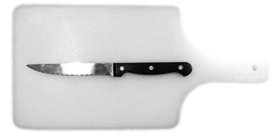
Figure 12: The original knife from which I designed the prototype
1.2.2. Modeling:
The basic idea here is was to leave space between the two sides of the knife handle so that it is possible to embed an accelerometer. For the modeling of the blade I used the XBee 1mW Chip Antenna - Series 1 dimensional drawings to get some indicative dimensions (1"*1"*0.25"). This caused the knife handle to be quite large and added an extra challenge to my final project question list : How to make a skinny wireless accelerometer that fits in a regular knife handle.
The knife handle consists of two parts that are casted separately so as to create a hollow interior. For that I designed four molds. First, the outside surface of the knife and its mirror and second, two different molds for the inside surface of the two handle sides. The idea was that the two knife handle pieces would snap together leaving a cavity which would be able to fit the accelerometer. In that way the accelerometer would be easily removable and replaceable.
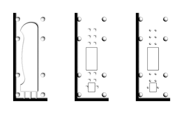
Figure 13: The hollow knife molds
1.2.3. Milling the rigid foam mold:
I used the PRSalpha 120-60 ShopBot at the CBA shop to mill the molds in rigid foam. I initially used Partworks 3D to make the toolpaths for the foam molds. Trying to make the milling faster, I initially set the tool diameter at 1/4", the pass depth at 1/2" and the stepover at 40%. Although the milling took only 25 minutes, most of the detail was lost, to an extend that the foam molds could not be used.
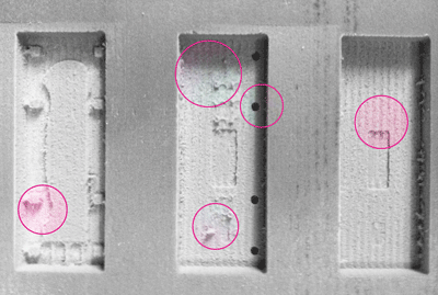
Figure 14: The problematic first mill (too aggressive)
In my second attempt, Josh helped me again to make the toolpaths in RhinoCAM. Learning from the unsuccesful last iteration, we decided to choose a finer bit (1/8" flat end), to reduce the stepover to 20% and the pass depth to 1/4", with much better results (albeit a much longer time - approximately 1,5 hour).
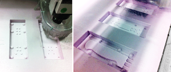
Figure 15: Milling the rigid foam at the CBA ShopBot
However, it was not after I had made the silicone rubber molds and done my first test cast that I realized that I had made a mistake in the molds, and instead of leaving a hollow space for the accelerometer I had done the inverse: i had created an inset volume in this area. I therefore had to remill the two interior molds.
This time I went back to Partworks 3D and used the same settings for the toolpaths except I made the stepover 40%, which speeded up the process without reducing the quality of the mold.
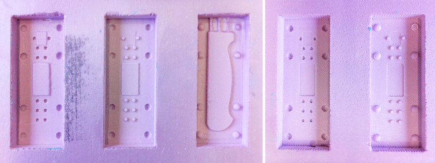
Figure 16: the rigid foam molds (on the left side is the wrong iteration and on the right side the corrected one)
1.2.4. Making the silicone mold:
Before casting the oomoo 25 in the foam I had to clean the rigid foam milled surfaces from thin scraps of material which had been left from the Shopbot. A good way to do this is to use the Hot Air gun and carefully melt them out. This process needs a lot of caution because there is the danger of holding the hot air gun either too close to the material or for too long and cause the foam to melt.One thing to take into consideration when pouring the silicone in the mold is to estimate the amount of oomoo you need. In my first try I realized it was not enough after I had started pouring the oomoo into the mold, and I had to make more. This two-phase pouring is generally not ideal.
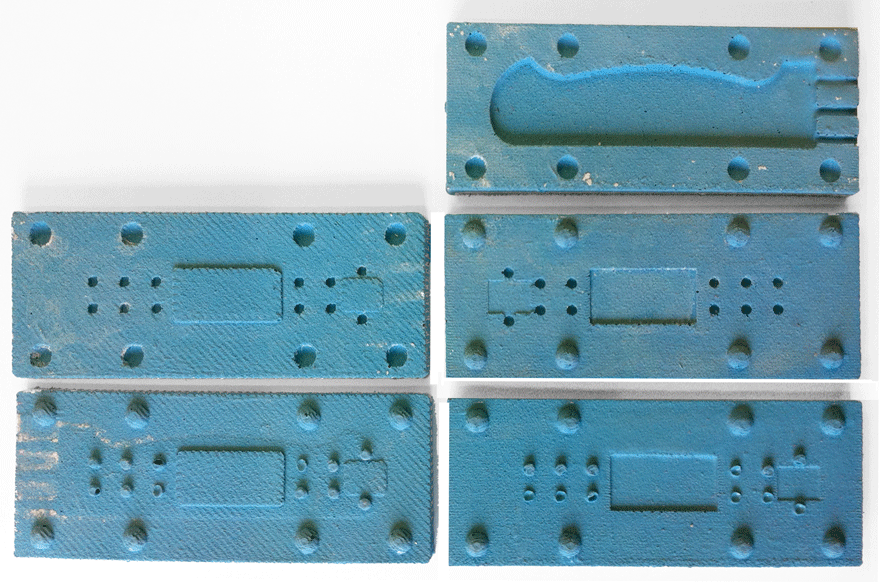
Figure 17: The rubber silicone hollow knife handle molds
1.2.5. Casting:
For casting I initially used Drystone.
This process was challenging because the material had to be spread evenly to a long and thin cavity. I used to pieces of plywood to clamp together the silicone rubber molds and then poured the Drystone in with a medicine dispenser. While injecting, I was gently shaking the mold so as to allow for the release of air.
However, although I managed to get the material to pour evenly, the piece broke multiple times when I tried to unmold it because of its length and very small width.
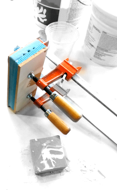
Figure 18: Casting the Drystone in the rubber silicone mold
After Sarah's suggestion, I mixed the Drystone with natural fabric which made the knife much more durable.
For the final iteration I would like to change some elements in the design of the knife (perhaps smaller and thicker) and experiment with a different material (probably plastic).

Figure 19: Adding natural fiber in the Drystone
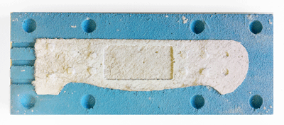
Figure 20: A first prototype of the knife handle
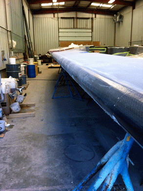
Last Tuesday (10/17/2011) I visited New England Boatworks, builders of composite sailing and power yachts. The visit was organized for the 4.116 studio at the MIT Department of Architecture, instructed by Mark Goulthorpe for which I am assisting. This term the srudents design a Visitor's Center for the America's Cup in Newport, RI. A special emphasis in the studio is on composites and their implications in the tectonics of buildings. The boat industry has a lot to offer in this direction. In this visit we had the chance to see the boats in different stages of their construction/repair; we even entered the oven where they were cooking a carbon fiver yacht. Below I am attaching some pictures from the Boat yard which I thought might be interesting in the context of the molding, casting and composites week.
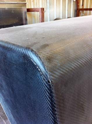
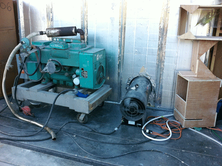
On Wednesday morning John and Tom gave us a tutorial on how to use the laser cutter. Here is a transcript of the notes that I kept along with some tips from personal experience.
3.1. Safety first:
It is quite usual to see a small flame when the laser is cutting the material. If a small flame worries you then you can open the lid and cover the flame with a piece of acrylic. If the flame is big or the material catches on fire then you open the lid, close the air valve and call 100.3.2. How to put the material on the laser bed:
The origin point is the top left corner. Make sure your material is the right size; in the Universal Laser Cutter at the CBA shop the bed is 32*18". You might need to use some tape to attach the material to the edges of the bed if it is not completely flat (this is for example very usual with cardboard)3.3. How to adjust the height of the laser bed:
Use the marked metal rod to measure the height between the cutting tool and the material you have placed on the laser cutter board. Press Z and use the Up and Down arrows to bring the cutting material to the edge of the metal rod. You will know that the height is right when the pin does not let the board to go any further up.
The check button moves to smaller digit precision for height refinements with the up and down arrows. Once you have found the right height press Z again to exit.3.4. How to send your files:
3.4.1. If you are using Inkscape:
1. Prepare your file and export it in 300dpi. Keep in mind that the white part is the one cut with precision so your offsets are "eating" off the black part.
2. Go to fab > run in terminal
3. Select the Universal laser cutter and define power and speed. Make sure that you set the pulses per inch (ppi) to be less than 500 if you are cutting cardboard. If you are cutting acrylic you can do almost 300.
4. Specify xmin and ymin. This is how far from the top left corner (origin) the machine will start cutting the file.
Hit make .uni
6. Send!3.4.2. If you are using CorelDraw (Windows):
1. Import your file
2. Make sure all your lines are Hairline (No thickness)
3. Optional step: You might want to offset your lines for precision. Go to Effects>Contour and do an Outside offset of 0.005 (or around that) Then do Arrange and break contour group apart.
4. Go to File>Print>Properties and set Power and Speed per color
Press Set to register your changes
6. Print!3.4.3. If you are using Rhino or AutoCAD (Windows) you can set the speed and power per layer through the print menu. Make sure you SKIP all the layers you do not want to cut and that you select the area you want to cut with a print window and that all your lines are 0 thickness or hairlines. In Rhino you can set the size of the print window and then Move it in the correct spot in the screen. You send your file by hitting print.
3.5 How to cut your files:
Find the right file! If you send multiple files you can navigate through them with the >> and << buttons.
2. Do a test run. It is recommended that you do a test run to confirm that the path is right. Just press the green button <|> while the lid is open.
3. Cut! If all looks fine close the lid and press <|> to cut.