![]()
![]()
- 1. project description
- 2. programming the board (codes)
1.1. General:
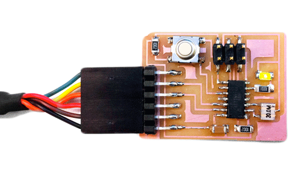
This week I made the echo hello-world board and I added an LED and a button. Then, I programmed the board to respond to button clicks and blink the LED light.

Figure 1: The Echo Hello World Board with the LED light ON. The board is powered through the FTDI cable
1.2. Designing the board in Eagle:
I used Adam Setapen's HelloFTDI board as the basis for the design of my board, where I also added an LED and a button using the Eagle PCB Software.
Schematic:
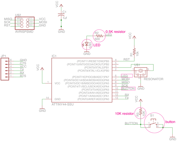
In the schematic view of Eagle, I added an LED to PA7. The LED light also needed a 0.5K resistor (you can also use an 1K resistor for LEDs) which prevents it from blowing up once the current starts flowing. After the LED I added the button to PA3 along with a 10K pull-up resistor. The pull up resistor pulls the signal high until the button is pressed. When the button is pressed, it goes to ground.
Useful commands in the schematic were:
add (add components from the libraries - I used the ng and the fab libraries);
net (make a new connection between components);
name (name with where you want to connect);
label (show the name of where you are connecting);
value (setting the value of various components eg. resistors)

Figure 2: Schematic view in Eagle PCB Software
Board:
After specifying the new connections in the schematic, the new components appeared in the board view of Eagle. Here I was able to route the LED, the button and their resistors and make the traces of my board. I exported the traces in monochrome .png with a resolution of 1000dpi after turning off the unecessary layers and keeping only the traces and the vias.
Useful commands in the board view were:
route (make a new connection between components in the board layout);
rats (ensure that you are done tracing and that there are no airwires);
ripup (delete a trace);
drc (check if you violate any of the fundamental design rules of the board e.g. spacing between the traces );
run bom (print out all the components that you need for the board)
Figure 3: Board view in Eagle PCB Software

Figure 4: The .png files with the traces of the board
1.3. Milling and stuffing the Board:
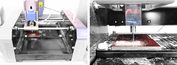
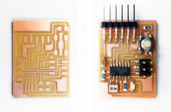
I used the MDX20 Roland Modela to mill the board and then soldered the components based on the Eagle file I had created. I followed my notes from the electronics production session for milling and soldering PCBs and the process was completed without any problems. The only part of the process that required attention was to identify the correct direction of the LED ligt, which as any diode, is directional.

Figure 5: Milling the board in the Modela

Figure 6: The milled board before and after soldering the components
1.4. Programming the board:
In order to program my new board I used the FabISP in-system programmer which I had made in the electronics production section.

Figure 7: Programming the board using the FabISP
> Hello Echo C Program:
I initially programmed my board with the hello.ftdi.echo program to test it. I successfully uploaded the program using Terminal, but I realized it was not working properly. The program was constantly echoing, and even more interestingly, it added noise in the echo when I was not holding the board still. Moritz helped me figure out that my board had a loose solder joint at the FTDI header. This caused the header to be very unstably connected to the board. I resoldered the joint and the problem was solved.
Figure 8: The result of the loose solder joint at the FTDI header
> C Code to Blink LED:
I consecutively modified an LED blinking program from Dimitris Papanikolaou's webpage, with the help of Moritz who explained the program to me and added some metas which made it more intutive. The first program on the board makes the LED be on when BUTTON is not pushed and blinks it when the BUTTON is pushed.
Figure 9: The blink LED program
> Blink LED - Counter C Program:
I further modified the program blinking the LED by adding a counter which keeps track of how many times the user has pressed the button and blinks the LED the same number of times. In this case, the LED is on when BUTTON is not pushed; the program keeps track of how many times the user has pressed the BUTTON since its launch and blinks the LED accordingly
Figure 9: The blink LED - Counter program
> Blink LED - Counter Arduino Program:
I wrote the same program in Arduino, by modifying the "Button" program provided as an arduino example. David Mellis' tutorial was very useful. Here I had to make a void method outside the loop() function in order to increment the counter keeping track of how many times the button has been pushed since the launch of the program.
Figure 11: A snapshot of the code in the Arduino environment
> Blink LED - Counter Modkit Program:
I also tried to see what the same program would look like in Modkit, which was introduced to us by Ed Baafi. This was only a quick try and I have not yet tested it with the board.
Figure 12: A snapshot of the code in the Modkit environmet (not yet tested!)> C Code to Blink LED: LED is on when BUTTON is not pushed and blinks when BUTTON is pushed
#include <avr/io.h>
#include <util/delay.h>#define bit_get(p,m) ((p) & (m))
#define bit_set(p,m) ((p) |= (m))
#define bit_clear(p,m) ((p) &= ~(m))
#define BIT(x) (0x01 << (x))int main()
{
//SETUP
//Button is on PA3
//LED is PB2
bit_set(PORTA,BIT(3)); //Turn button pullup resistor on by setting PA3(input) high
bit_set(DDRA,BIT(7)); //Enable output on the LED pin (PB2)
//LOOP
while (1)
{
if(bit_get(PINA,BIT(3)))//button is not pushed
{
bit_set(PORTA,BIT(7));//LED is on
}
else // button is pushed
{
bit_set(PORTA,BIT(7));//LED is on
_delay_ms(80);//wait 80msec
bit_clear(PORTA,BIT(7));//LED is off
_delay_ms(80);
}
}
}> Blink LED - Counter C Code: LED is on when BUTTON is not pushed; the program keeps track of how many times the user has pressed the BUTTON since its launch and blinks the LED accordingly
#include <avr/io.h>
#include <util/delay.h>#define bit_get(p,m) ((p) & (m))
#define bit_set(p,m) ((p) |= (m))
#define bit_clear(p,m) ((p) &= ~(m))
#define BIT(x) (0x01 << (x))int main()
{
//SETUP
//Button is on PA3
//LED is PB2
bit_set(PORTA,BIT(3)); //Turn button pullup resistor on by setting PA3(input) high
bit_set(DDRA,BIT(7)); //Enable output on the LED pin (PB2)int i=0;
//LOOP
while (1)
{
int j=0;
if(bit_get(PINA,BIT(3)))//button is not pushed
{
bit_set(PORTA,BIT(7));//LED is on
}
else // button is pushed
{
while (j<=i)
{
bit_set(PORTA,BIT(7));//LED is on
_delay_ms(80);//wait 80msec
bit_clear(PORTA,BIT(7));//LED is off
_delay_ms(80);
j = j+1;
}
i+=1;
}
}
}> Blink LED - Counter Arduino Code: LED is on when BUTTON is not pushed; the program keeps track of how many times the user has pressed the BUTTON since its launch and blinks the LED accordingly
/*
created 2005
by DojoDave <http://www.0j0.org>
modified 31 Oct 2011
by Theodora Vardouli
This example code is in the public domain.
http://www.arduino.cc/en/Tutorial/Button
*/// constants won't change. They're used here to
// set pin numbers:
const int buttonPin = 3; // the number of the pushbutton pin
const int ledPin = 7; // the number of the LED pinint buttonState = 0;// variable for reading the pushbutton status
int i = 0; // initialize countervoid setup() {
// initialize the LED pin as an output:
pinMode(ledPin, OUTPUT);
// initialize the pushbutton pin as an input:
pinMode(buttonPin, INPUT);
}void loop(){
// read the state of the pushbutton value:
buttonState = digitalRead(buttonPin);
counter();
// if the pushbutton is not pressed
if (buttonState == HIGH) {
// turn LED on:
digitalWrite(ledPin, HIGH);
}
else {
// if the button is pressed
//repeat as many times as the user has pressed the button so far
int j=0;
while (j<i)
{
//blink the LED
digitalWrite(ledPin, HIGH); // turn LED on
delay(800); // wait 800ms
digitalWrite(ledPin, LOW); // turn LED off
delay(800); // wait 800ms
j++;
}
}
}//counter method incrementing the i counter every time the button is pushed
void counter()
{
buttonState = digitalRead(buttonPin);
// if the pushbutton is not pressed
if (buttonState == LOW) {
// increment counter
i++;
}
}
On Wednesday morning John and Tom gave us a tutorial on how to use the laser cutter. Here is a transcript of the notes that I kept along with some tips from personal experience.
3.1. Safety first:
It is quite usual to see a small flame when the laser is cutting the material. If a small flame worries you then you can open the lid and cover the flame with a piece of acrylic. If the flame is big or the material catches on fire then you open the lid, close the air valve and call 100.3.2. How to put the material on the laser bed:
The origin point is the top left corner. Make sure your material is the right size; in the Universal Laser Cutter at the CBA shop the bed is 32*18". You might need to use some tape to attach the material to the edges of the bed if it is not completely flat (this is for example very usual with cardboard)3.3. How to adjust the height of the laser bed:
Use the marked metal rod to measure the height between the cutting tool and the material you have placed on the laser cutter board. Press Z and use the Up and Down arrows to bring the cutting material to the edge of the metal rod. You will know that the height is right when the pin does not let the board to go any further up.
The check button moves to smaller digit precision for height refinements with the up and down arrows. Once you have found the right height press Z again to exit.3.4. How to send your files:
3.4.1. If you are using Inkscape:
1. Prepare your file and export it in 300dpi. Keep in mind that the white part is the one cut with precision so your offsets are "eating" off the black part.
2. Go to fab > run in terminal
3. Select the Universal laser cutter and define power and speed. Make sure that you set the pulses per inch (ppi) to be less than 500 if you are cutting cardboard. If you are cutting acrylic you can do almost 300.
4. Specify xmin and ymin. This is how far from the top left corner (origin) the machine will start cutting the file.
Hit make .uni
6. Send!3.4.2. If you are using CorelDraw (Windows):
1. Import your file
2. Make sure all your lines are Hairline (No thickness)
3. Optional step: You might want to offset your lines for precision. Go to Effects>Contour and do an Outside offset of 0.005 (or around that) Then do Arrange and break contour group apart.
4. Go to File>Print>Properties and set Power and Speed per color
Press Set to register your changes
6. Print!3.4.3. If you are using Rhino or AutoCAD (Windows) you can set the speed and power per layer through the print menu. Make sure you SKIP all the layers you do not want to cut and that you select the area you want to cut with a print window and that all your lines are 0 thickness or hairlines. In Rhino you can set the size of the print window and then Move it in the correct spot in the screen. You send your file by hitting print.
3.5 How to cut your files:
Find the right file! If you send multiple files you can navigate through them with the >> and << buttons.
2. Do a test run. It is recommended that you do a test run to confirm that the path is right. Just press the green button <|> while the lid is open.
3. Cut! If all looks fine close the lid and press <|> to cut.