![]()
![]()
- 1. 3d printing
- 2. 3d scanning
1.1. Concept:
For the 3d printing assignment I made a thin chain of different components which is printed in its box. I took the challenge of fitting a long chain (total length 9 1/2") in a 1*1*1" box as a fascinating constraint and I designed a series of nested elements which are packed in the box so as to form a folded chain. When the support material is removed, the lid of the box opens and the chain can be pulled out.
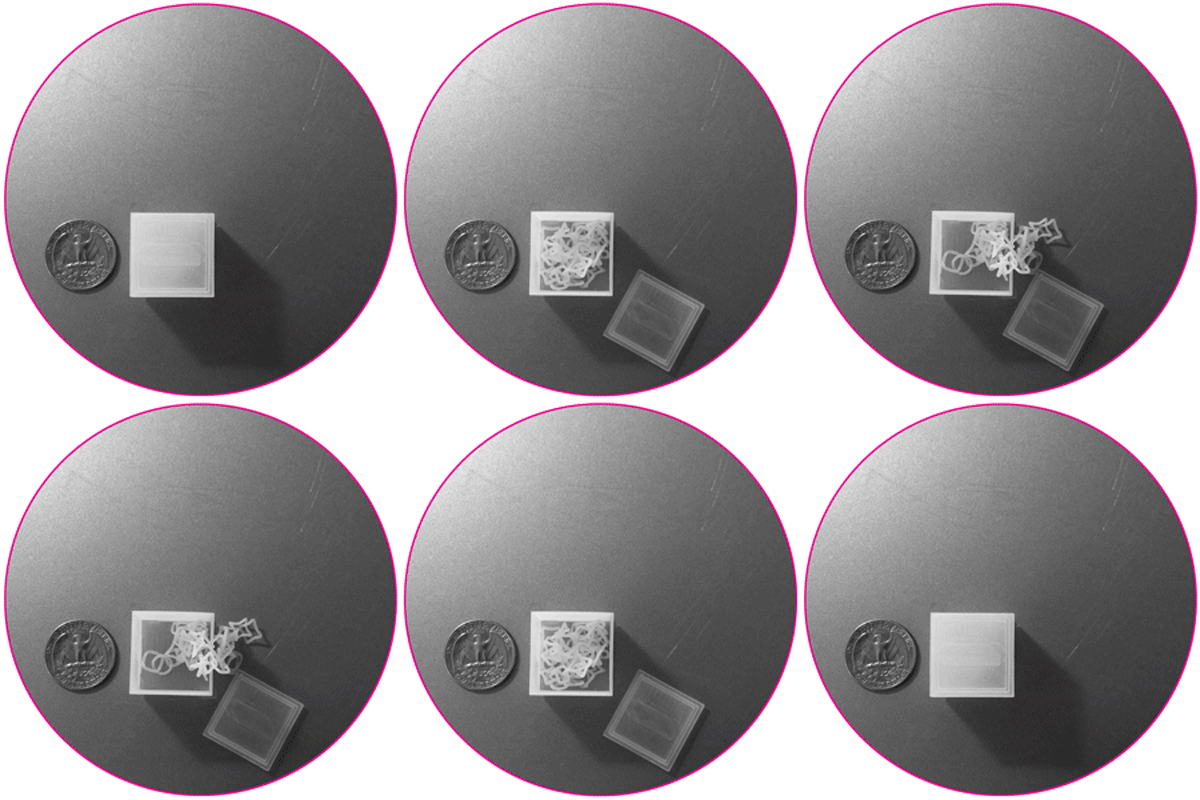
Figure 1:The 9 1/2" chain and the 1*1*1" box
1.2. Designing the rings:
I used Rhino 3D to first create the components of the chain. I wanted to create the impression of an element morphing from one shape to another so I started with a rounded rectangle and moving the control points of the curve on a 1/32" grid in incremental steps, transitioned to a circle. The outer bounding box of all the elements is 1/4".
Figure 2: Top - the repertoire of ring curves; the movement of the control points on a 1/32" allows for the morphing from a rounded rectangle to a circle . Bottom - the 0.03" diameter rings produced by the curves
In order to thicken the curves, I used the "pipe" command which sweeps the curve with a circle. I specified the diameter of the circle to be 0.03" which was close to the thinnest I could get and still ensure the rigidity of the rings. I had to exclude some of the curves from the piping process, either because their geometry was too acute at parts, or because the inner radius of the ring became too narrow for it to be able to be nested with another ring.
Figure 3: The final chain components
1.3. Modeling the box:
After having designed the ring components of the chain I had to nest them in the 1*1*1" box. I tried to make the walls of the box as thin as possible (0.03") so as to leave more space for the folded chain in its interior. I separated the lid from the box by 0.015" so that the lid can be lifted. I also left thin 1/4" slits at the bottom of the box so that the melting support material could pour out of the box.Figure 4: The 1*1*1" box containing the chain
1.4. Packing the rings in the box:
This was a challenging process because the nesting and packing had to satisfy a series of constraints:
1. connect each ring with the component that comes before it and the component that comes after it exclusively. This ensures that the rings are connected to form a linear chain and that there are no instances where the chain self-intersects or creates internal loops.
2. leave enough distance between the rings and the rings and the internal faces of the box so that they are separated by at least two layers of supporting material (0.015")
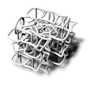
Figure 5: The folded chain as a result of the nesting of rings with given tolerances
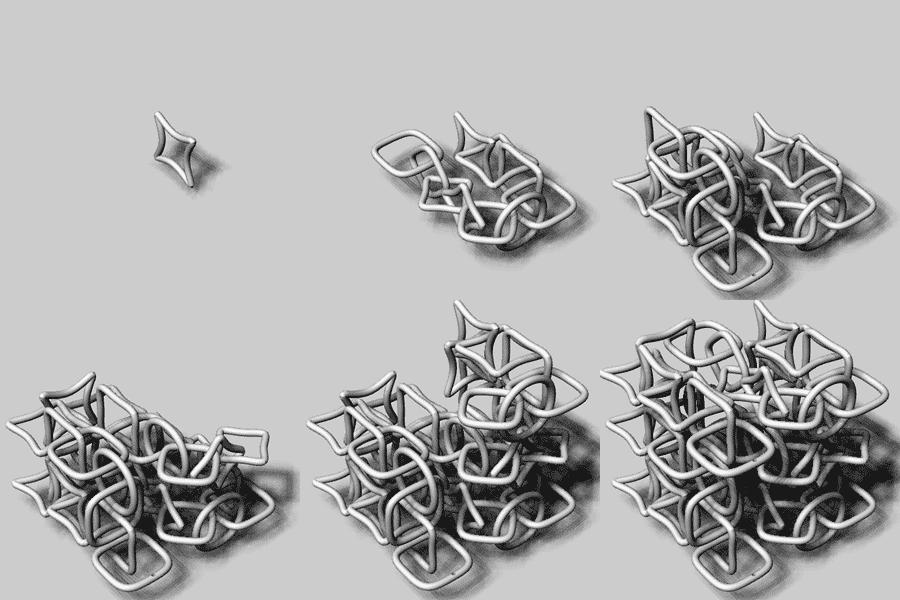
Figure 6: Process of connecting the ring components and folding the chain in the box
1.5. 3d-printing:
I used the Invision si2 3d printer at the CBA shop. When I went to collect my print the lid was easily removable but the chain seemed to be stuck to the walls of the box and many of the rings seemed clamped. At first I thought that I had not used the proper tolerances in the model and that parts had been printed together. However, I soon realized that the issue was that the support material (wax) had not been completely removed and had solidified inhibiting the elements from moving.
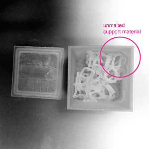
Figure 7: The unmelted support material (wax) trapping the chain in the box
I put the print in the oven at 150 degrees for another 15 minutes and then while the wax was still hot, I pulled the chain out of the box with a tweezer and quickly started separating the rings from each other. During this process the chain broke in two, which repurposed it from a necklase to earrings.
In order to clean the pieces more, I placed them on a piece of cloth and used the heat gun to melt the rest of the wax away. After cleaning the box has a very interesting translucency.
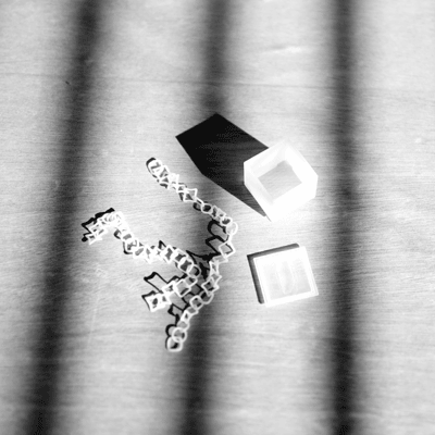
Figure 8: The chain and the box after the cleaning of the wax
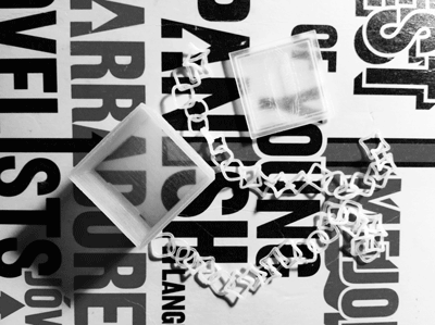
Figure 9: The chain and the box after the cleaning of the wax; the box is almost transparent because of its small thickness (0.03")
2.1. Tutorial at the CBA:
On Tuesday morning John Difrancesco and Tom Lutz showed us how to use the Konica Minolta 3D Digitizer, with the Geomagic software. I brought a wooden mannequin for testing. We decided to scan only its legs for demonstration. The result was very good besides the initial anxiety about the model moving while the table was rotating during the multi-shot scan. Tom also showed us the NextEngine 3d Laser Scanner, which he used to scan a matchbox. Compared to the Minolta, the scanner is slower with relatively worse software support (ScanStudio HD). Below are some snapshots from the tutorial.
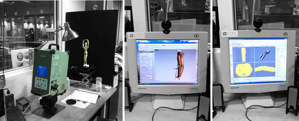
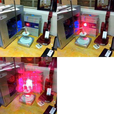
Figure 9: Left - testing the Konica Minolta Digitizer with a mannequin; Right - testing the Next Engine 3d Laser Scanner with a matchbox
2.2. Artist's mannequin with Hand Held Z-Corp 3d Scanner:
After having tried the mannequin at the Konica Minolta with John, I decided to use the Architecture Shop Hand Held Z-Corp 3d Scanner, which comes with the ZScan 3d Digitizing Software. The Scanner requires the following steps:
1. sensor calibration with an image that comes with the scanner package
2. sensor configuration with the object which is being scanned
3. positioning features scanning; these are the white stickers that you see in the image below. They are used to create a coordinate system for the scanner in relation to the geometry of the object
4. object scanning
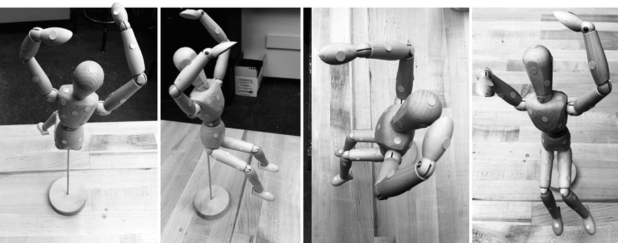
Figure 10: The mannequin covered with stickers which operate as positioining features

Figure 10: Snapshots from the ZScan Environment - Left: scanning the positioning features; Right: Scanning the object
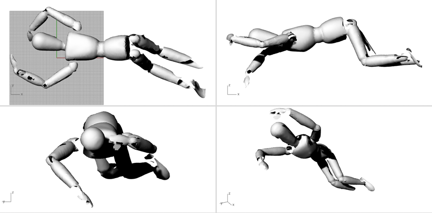
Figure 11: The .stl model from the mannequin scan with the ZCorp hand-held 3d scanner
I tried two times but the result that I got was not satisfactory for the entire figure. Some parts of it were scanner smoothly and accurately but other parts were left open although I persistently tried to fill them in while scanning. One problem was the metal rod that was holding the mannequin which was occasionally shooting off reflections causing noise in the scan.
2.3. Artist's mannequin with Konica Minolta Digitizer (take 2):
In my second attempt at the Konica Minolta, the attachement of the mannequin to the vertical metal rod had become even looser, causing the object to move while the plate was rotating. Although the indvidual scans were very good, the stiching between them became very problematic.
Figure 12: An .stl model from the Konica Minolta Digitizer; the motion of the model during the scanning caused problems in the stitching of the pieces
2.4. Artist's mannequin with Konica Minolta Digitizer (take 3):
This time I made sure to change the position of the mannequin so that it is more stable and to put some hot glue at the point where the supporting metal rod meets the mannequin. The result was much better.
Figure 13: The .stl model from the mannequin scan with the Konica Minolta Digitizer
1.5. Russian Doll with Konica Minolta:
After having scanned the mannequin I scanned a Russian Doll thatn I have had since I can remember myself. I used 90 degrees multishot scan, which came out good. I used geomagic to patch some minor holes.
Figure 14: Scanning and using the Geomagic Software at the CBA shop
Figure 15: The .stl model from the russian doll scan with the Konica Minolta Digitizer
On Wednesday morning John and Tom gave us a tutorial on how to use the laser cutter. Here is a transcript of the notes that I kept along with some tips from personal experience.
3.1. Safety first:
It is quite usual to see a small flame when the laser is cutting the material. If a small flame worries you then you can open the lid and cover the flame with a piece of acrylic. If the flame is big or the material catches on fire then you open the lid, close the air valve and call 100.3.2. How to put the material on the laser bed:
The origin point is the top left corner. Make sure your material is the right size; in the Universal Laser Cutter at the CBA shop the bed is 32*18". You might need to use some tape to attach the material to the edges of the bed if it is not completely flat (this is for example very usual with cardboard)3.3. How to adjust the height of the laser bed:
Use the marked metal rod to measure the height between the cutting tool and the material you have placed on the laser cutter board. Press Z and use the Up and Down arrows to bring the cutting material to the edge of the metal rod. You will know that the height is right when the pin does not let the board to go any further up.
The check button moves to smaller digit precision for height refinements with the up and down arrows. Once you have found the right height press Z again to exit.3.4. How to send your files:
3.4.1. If you are using Inkscape:
1. Prepare your file and export it in 300dpi. Keep in mind that the white part is the one cut with precision so your offsets are "eating" off the black part.
2. Go to fab > run in terminal
3. Select the Universal laser cutter and define power and speed. Make sure that you set the pulses per inch (ppi) to be less than 500 if you are cutting cardboard. If you are cutting acrylic you can do almost 300.
4. Specify xmin and ymin. This is how far from the top left corner (origin) the machine will start cutting the file.
Hit make .uni
6. Send!3.4.2. If you are using CorelDraw (Windows):
1. Import your file
2. Make sure all your lines are Hairline (No thickness)
3. Optional step: You might want to offset your lines for precision. Go to Effects>Contour and do an Outside offset of 0.005 (or around that) Then do Arrange and break contour group apart.
4. Go to File>Print>Properties and set Power and Speed per color
Press Set to register your changes
6. Print!3.4.3. If you are using Rhino or AutoCAD (Windows) you can set the speed and power per layer through the print menu. Make sure you SKIP all the layers you do not want to cut and that you select the area you want to cut with a print window and that all your lines are 0 thickness or hairlines. In Rhino you can set the size of the print window and then Move it in the correct spot in the screen. You send your file by hitting print.
3.5 How to cut your files:
Find the right file! If you send multiple files you can navigate through them with the >> and << buttons.
2. Do a test run. It is recommended that you do a test run to confirm that the path is right. Just press the green button <|> while the lid is open.
3. Cut! If all looks fine close the lid and press <|> to cut.