![]()
![]()
- 1. project description
- 2. programming the board (C code)
1.1. General:
The assignment for this week was to add an output device to a microcontoller board and program it to do something. Thinking also about my final project where I want to embed an LED array in a cutting kitchen board which will respond to an accelerometer-knife I focused on Charlieplexing. I redesigned Neil's LED Array Board in the Eagle PCB Software and I added a button so that the user can switch can change the characteristics of the LED cycle by clicking. I also tried to do an LED array which would cover a larger surface than that of a PCB board. I will need this for my final project as well. I spaced out the traces so that the LEDs cover a 5*7.5" area and then used the vinylcutter to make them. I programmed the first board in C but unfortunately could not get the vinylcut one to work (yet). After debugging I realized that one of the thin traces at the 4-pin header was cut. Hopefully I will manage to fix it soon (Monday morning). Finally, I made a new FabISP because I ripped off the traces of the old one at the 6-pin header.
Figure 1: The Charlieplex LED array; the LEDs are drawing power from a 5V battery
1.1.a Designing the board in Eagle:
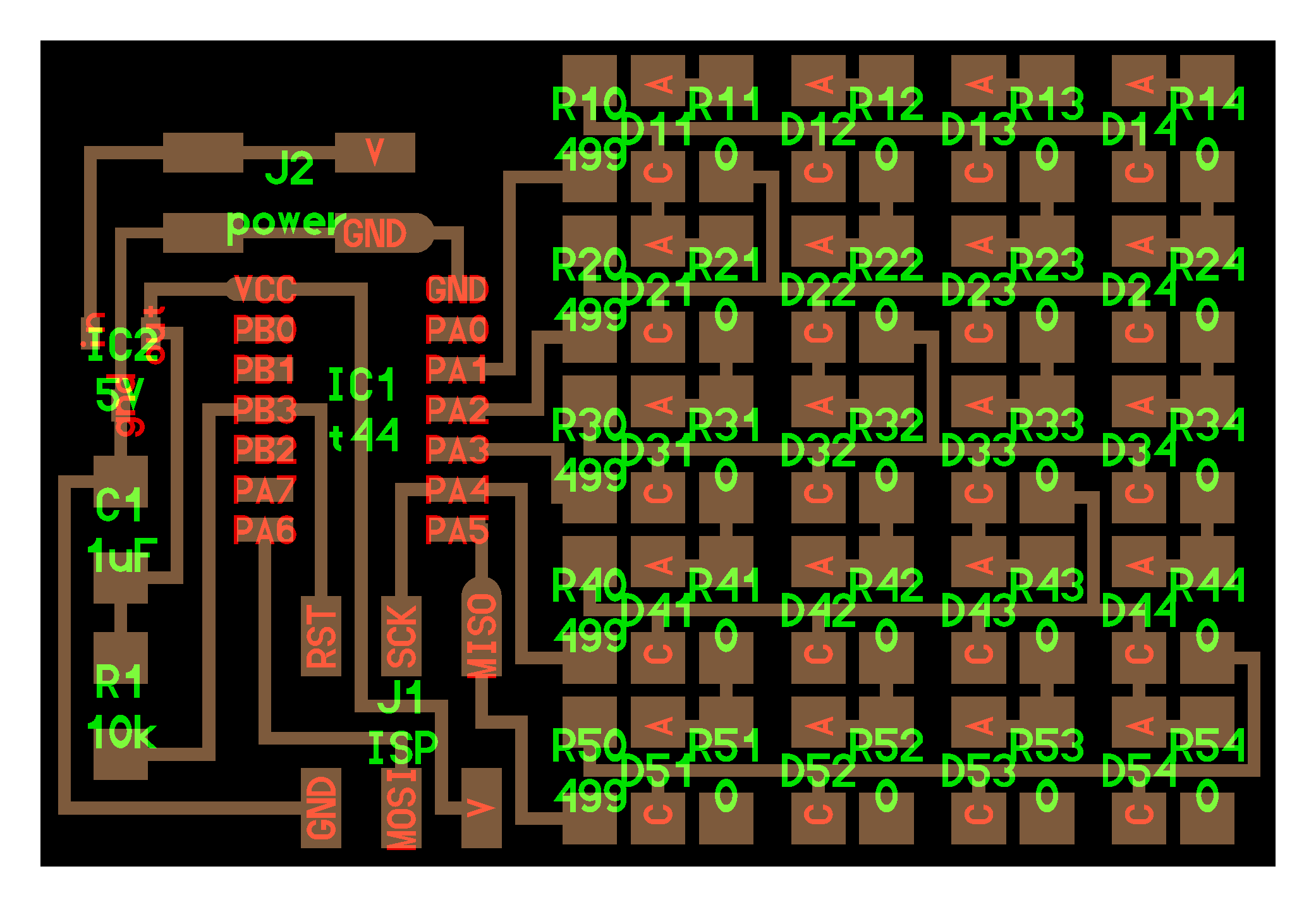
Schematic:
I used Neil's Hello.array.44 as the basis for the design of my board. I used Eagle to redesign the board and added a Button at PA7 of the Attiny 44, which was free. Remaking the schematic of the board was very helpful because I got a much better understanding of the components and connections between them.
Figure 2: Schematic view in Eagle PCB Software
Board:
After specifying the new connections in the schematic, the new components appeared in the board view of Eagle. Here I was able to route the the button and its resistors and make the traces of my board. I exported the traces in monochrome .png with a resolution of 1000dpi after turning off the unecessary layers and keeping only the traces. I did something wrong with the tolerances in the Design Rule Check because it did not give me any errors although as I realized after cutting the board there was not enough space between some of the traces. Routing the board was a little challenging in the beginning but went very smoothly after I moved the LED rows and the rest of the components in their proper positions.
Figure 3: The unrouted board in Eagle
Figure 4: The routed board in Eagle
Figure 5: The .png file with the traces of the new board (this is the second and correct iteration where some of the traces had to be spaced more)
1.1.b. Milling and stuffing the Board:
I used the MDX20 Roland Modela to mill the board and then soldered the components based on the Eagle file I had created. My first attempt was unsuccesful for two reasons: first, because of an uneven sacrificial layer the Modela did not cut the board evenly leaving some areas at the top left corner where the copper was not fully removed and second, that some of the traces needed to be spaced more and were printed as linked by the Modela. The worst part is that I realized this problem after having soldered all the resistors and LEDs!
Figure 6: Linked traces requiring more spacing
Figure 7: The second iteration of the board after having revised the traces
1.1.c. Programming the board:
In order to program my new board I used my new FabISP in-system programmer. I had to replace the old one after ripping off the 6-pin header.
Figure 8: The old and new FabISP
> Hello Array C Program:
I initially programmed my board with the hello.array.44 to test it. It worked very well until one point where the voltage regulator was overheated and started melting. I am considering replacing it with the larger 5V regulator. I was a little unclear about which one to use because ofthe discrepancy of the shape with the name of the regulator in the initial design.
Figure 9: The board running Neil's code
> C Code to Control LED Array with Button:
I consecutively modified Neil's code and combined it with the C code that I had written for the blinking LED in the embedded programming week. The new code does the following: When the button is not pressed it keeps the LEDs on. Every time the user presses the button the output in the LED array changes. The way that I wrote it is that the button keeps track of how many times it has been pushed by the user since the beginning of the flashing program execution and manages the delay of the LED flashing accordingly. The full code in C is in the next page. However, the result that I am getting is different than the one I am planning on. I manage to make the LEDs loop 3 times (counter k<=2)but although I expected the delay to increase each time by 100, it seems to increase and decrease erratically.
Figure 10: The board running my C code
The problem seems to be an integer overflow. I decreased the delay multiplier factor from 100 to 50. Now it takes more cycles where the Delay is increased at every button push before the overflow.
Figure 11: Delaying integer overflow
1.2.a Larger LED array:
As mentioned above, I increased the spacing between the LEDs so that they occupy a 5*7.5" area. I used Adobe Illustrator to design the new traces. After laying them out on the sheet, I used the GX-24 Roland Vinyl Cutter to cut the traces out of copper. The settings that I used were force 35 and velocity 2.5, which worked very well. I used a thin plastic as the surface where I placed the traces. This surface was particularly easy for weeding but made the soldering process very hard. The solder iron kept melting the plastic and I had to use large amounts of hot glue to stabilize the traces. The soldering process took many hours as problems were constantly occuring(traces getting cut, plastic melting).Instead of using an epoxy film layer between the two layers of copper, I used small epoxy squares to separate the two copper layers so as to avoid shortcircuiting.
In the process and although I was trying to repair any damages I noticed, I tore a trace close to the 4-pin header, which was very hard to see. Therefore I could not program the vinyl board. I will try to fix it tomorrow morning.
Figure 11: The Vinylcutter settings; snapshot from Fab modules
Figure 12: Vinyl Cutting and weeding
Figure 13: The vinylcut 5 * 7.5" board
> Controll Array through Button C Code: LED array is off when BUTTON is not pushed; the program keeps track of how many times the user has pressed the BUTTON since its launch and bases the delay of the LED array flashing on that
//
//
// hello.array.44.c
//
// Charlieplex LED array hello-world
//
//created 13 Nov 2011
//by Neil Gerschenfeld
//modified 31 Oct 2011
//by Theodora Vardouli
//
// (c) Massachusetts Institute of Technology 2010
// Permission granted for experimental and personal use;
// license for commercial sale available from MIT.
//#include <avr/io.h>
#include <util/delay.h>#define output(directions,pin) (directions |= pin) // set port direction for output
#define input(directions,pin) (directions &= (~pin)) // set port direction for input
#define set(port,pin) (port |= pin) // set port pin
#define clear(port,pin) (port &= (~pin)) // clear port pin
#define pin_test(pins,pin) (pins & pin) // test for port pin
#define bit_test(byte,bit) (byte & (1 << bit)) // test for bit set
#define bit_get(p,m) ((p) & (m))
#define bit_set(p,m) ((p) |= (m))
#define bit_clear(p,m) ((p) &= ~(m))
#define BIT(x) (0x01 << (x))#define led_delay() _delay_ms(1) // LED delay
#define led_port PORTA
#define led_direction DDRA#define A (1 << PA1) // row 1
#define B (1 << PA2) // row 2
#define C (1 << PA3) // row 3
#define D (1 << PA4) // row 4
#define E (1 << PA5) // row 5void flash(uint8_t from, uint8_t to, uint8_t delay) {
//
// source from, sink to, flash
//
static uint8_t i;
set(led_port,from);
clear(led_port,to);
output(led_direction,from);
output(led_direction,to);
for (i = 0; i < delay; ++i)
led_delay();
input(led_direction,from);
input(led_direction,to);
}void led_cycle(uint8_t number, uint8_t delay) {
//
// cycle through LEDs
//
uint8_t i;
for (i = 0; i < number; ++i) {
flash(B,A,delay);
flash(C,A,delay);
flash(D,A,delay);
flash(E,A,delay);
flash(A,B,delay);
flash(C,B,delay);
flash(D,B,delay);
flash(E,B,delay);
flash(A,C,delay);
flash(B,C,delay);
flash(D,C,delay);
flash(E,C,delay);
flash(A,D,delay);
flash(B,D,delay);
flash(C,D,delay);
flash(E,D,delay);
flash(A,E,delay);
flash(B,E,delay);
flash(C,E,delay);
flash(D,E,delay);
}
}
int main(void)
{
//
// set clock divider to /1
//
CLKPR = (1 << CLKPCE);
CLKPR = (0 << CLKPS3) | (0 << CLKPS2) | (0 << CLKPS1) | (0 << CLKPS0);
//
bit_set(PORTA,BIT(7));//Turn button pullup resistor on by setting PA7(input) high
bit_set(DDRA,BIT(1)); //Enable output on the LED pin (PA1)
bit_set(DDRA,BIT(2)); //Enable output on the LED pin (PA2)
bit_set(DDRA,BIT(3)); //Enable output on the LED pin (PA3)
bit_set(DDRA,BIT(4)); //Enable output on the LED pin (PA4)
// main loop
int j=0;
while (1)
{
if (bit_get(PINA,BIT(7)))//button is not pushed
{
bit_clear(PORTA,BIT(1));//off
bit_clear(PORTA,BIT(2));//off
bit_clear(PORTA,BIT(3));//off
bit_clear(PORTA,BIT(4));//off
}
else // button is pushed
{ int k=0;
while (k<=2)
{
led_cycle(1,j*100); //overflow!
k = k+1;
}
j = j+1;
}
}
}
On Wednesday morning John and Tom gave us a tutorial on how to use the laser cutter. Here is a transcript of the notes that I kept along with some tips from personal experience.
3.1. Safety first:
It is quite usual to see a small flame when the laser is cutting the material. If a small flame worries you then you can open the lid and cover the flame with a piece of acrylic. If the flame is big or the material catches on fire then you open the lid, close the air valve and call 100.3.2. How to put the material on the laser bed:
The origin point is the top left corner. Make sure your material is the right size; in the Universal Laser Cutter at the CBA shop the bed is 32*18". You might need to use some tape to attach the material to the edges of the bed if it is not completely flat (this is for example very usual with cardboard)3.3. How to adjust the height of the laser bed:
Use the marked metal rod to measure the height between the cutting tool and the material you have placed on the laser cutter board. Press Z and use the Up and Down arrows to bring the cutting material to the edge of the metal rod. You will know that the height is right when the pin does not let the board to go any further up.
The check button moves to smaller digit precision for height refinements with the up and down arrows. Once you have found the right height press Z again to exit.3.4. How to send your files:
3.4.1. If you are using Inkscape:
1. Prepare your file and export it in 300dpi. Keep in mind that the white part is the one cut with precision so your offsets are "eating" off the black part.
2. Go to fab > run in terminal
3. Select the Universal laser cutter and define power and speed. Make sure that you set the pulses per inch (ppi) to be less than 500 if you are cutting cardboard. If you are cutting acrylic you can do almost 300.
4. Specify xmin and ymin. This is how far from the top left corner (origin) the machine will start cutting the file.
Hit make .uni
6. Send!3.4.2. If you are using CorelDraw (Windows):
1. Import your file
2. Make sure all your lines are Hairline (No thickness)
3. Optional step: You might want to offset your lines for precision. Go to Effects>Contour and do an Outside offset of 0.005 (or around that) Then do Arrange and break contour group apart.
4. Go to File>Print>Properties and set Power and Speed per color
Press Set to register your changes
6. Print!3.4.3. If you are using Rhino or AutoCAD (Windows) you can set the speed and power per layer through the print menu. Make sure you SKIP all the layers you do not want to cut and that you select the area you want to cut with a print window and that all your lines are 0 thickness or hairlines. In Rhino you can set the size of the print window and then Move it in the correct spot in the screen. You send your file by hitting print.
3.5 How to cut your files:
Find the right file! If you send multiple files you can navigate through them with the >> and << buttons.
2. Do a test run. It is recommended that you do a test run to confirm that the path is right. Just press the green button <|> while the lid is open.
3. Cut! If all looks fine close the lid and press <|> to cut.