Week Four / Five: Final Project Research / Make Something Big!
Weeks 4 and 5 were combined, and thus we got two assignments: do background research on our final project, as well as make something big. In lecture we went over CNC (computer numerical control) techniques and a short intro on types of CAM (computer aided manufacturing) programs, and in the lab section we were shown the basics of operating the waterjet and ShopBot. I've already done a lot of waterjetting prior to the class, so I decided to come up with something that would use the ShopBot to make something big.
I had a 4'x5' sheet of really nice (AB or AA, I forget which) 3/4" plywood -- the wood itself is probably over a year old, left over from a project and had been collecting dust, waiting for something interesting. I decided that it'd be enough wood for a desk, if I made the legs out of the sheet of OSB that we were given. I figured that it'd be boring to make a square desk, because those are pretty commonplace, and opted to make a shark-shaped top for my desk. I ended up sketching the shark on paper and optimizing it for a desk-like-shape, and then scanning it in and tracing it:
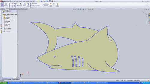
I then modelled the rest of the table in Solidworks:
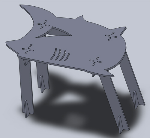
And generated drawings in R12 .dwg format. Here are two links to .pdf files that contain the drawings: [one] [two].
I took these files to the ShopBot computer and opened them up in Partworks to add fillets and make the toolpaths. I first made a toolpath with just two of the bottom support pieces as test cuts to make sure my press fits were indeed press fits, and then I made the rest of the cut.
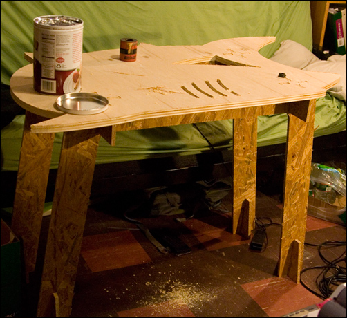
I had to do a little bit of finishing on the pieces -- the bottom side had slightly burred edges, and needed to be sanded down. However, a quick test of fit showed that overall, it worked pretty well. One mistake I made was not providing enough length on the bottom leg pieces, because the table is not completely stiff front to back. I think if I make the four bottom supports into two and make them taller, that'll solve the problem pretty easily. Everything else seems to work pretty smoothly, and this table functions quite nicely as something that I can quickly disassemble and store if I need more floorspace or something.
The shark-desk didn't deter me from using the waterjet though! Two friends and I decided to hack together a pasta maker out of a meat grinder and a window motor. We got to make the motor coupler and pasta-shaping plates. I did the design and machining of the coupler, and a friend drew up the pasta-shaping plates for me to waterjet. Soon we will make an actual stand for the thing so we don't have to awkwardly hold it. Here are some photos of the waterjetting and the pasta-making:
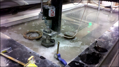
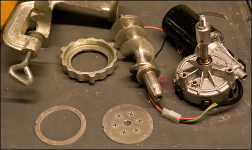
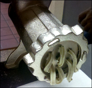
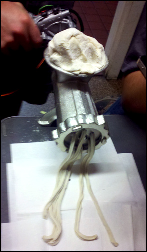
I think the shop should get one of these so I can make rotini shapes...(and because 5-axis waterjets are so awesome).

On the final project front, [this link] contains someone else's DIY CNC hot wire cutter. The idea behind it is pretty simple -- you put two sets of Y-Z linear stages in parallel, have each side hold onto the wire, and move both sides in sync. The FoamLinx cutter uses a spring to tension the wire, which seems a little sketchy because springs work better in compression than in tension (springs in tension are more likely to elastically deform than springs in tension). I think I'd like to try a system that uses a system similar to how guitars get tensioned, where a worm gear turns a normal gear to tension the string. This does mean that, much like a guitar, you'd have to re-tension every so often, and the wire may possibly snap after many uses, but using a spring instead means you're depending on the spring constant to pull the wire taut and that spring constant could change if you've plastically deformed the spring.
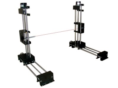
Image courtesy of www.8linx.com
On the electronics front, I'm thinking of doing something like 120VAC -> transformer -> rectifier -> buck converter with feedback to allow a controllable constant current to flow into the wire. For controls logic, I'll use a separate 120VAC -> transformer -> rectifier -> 5V (or whatever voltage that the chips I choose will demand) to provide that voltage. I suspect that the logic chips will SMT components on a milled board, but the components for controlling the current flow into the cutting wire will probably be soldered onto a perf board to allow for higher amperage safely.