Week Seven: Embedded Programming
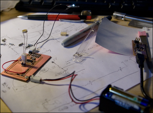
Our assignment this week was to add an LED + pull-up resistor and a switch to a basic attiny44 board, and program it. I decided to do just that, with a slight twist: I was going to use a 1W LED for the LED, and use a photoresistor as the switch to vary the LED's brightness. I wanted a headlamp-hat, where I could go into somewhere dark and the headlamp would automatically adjust to be brighter, and step out into the light and the headlamp automatically be dimmer.
This started out with a schematic, which got translated into a .png image for the vinylcutter. THe reason that the resistor + zener diode are all the way out there is because I originally intended for those components to wrap all the way around the hat to the back so I could carry the battery in the back.
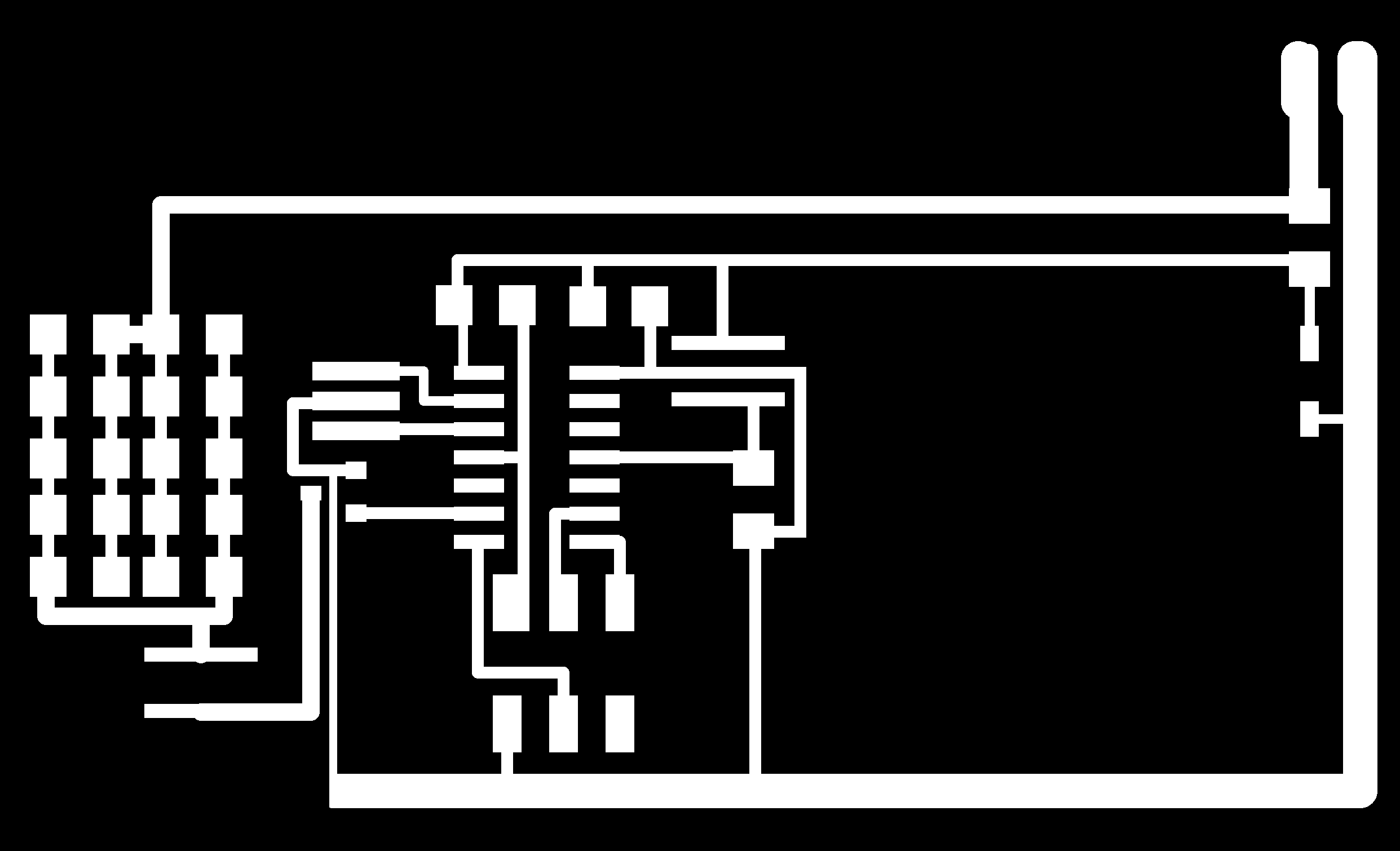
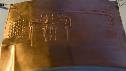
I first vinyl cut this because I wanted it to be flexible for the hat, but kept running into problems with too much force or not enough force -- too much force caused the traces to rip up, and too little meant it didn't separate from the sheet. I was literally changing the force by one, and it would go from ripping up to not fully cutting. The ripups would occur when a cut came too close to another trace that was already cut, and the copper wasn't well-stuck to its backing.
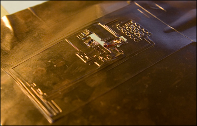
Eventually, some combination of making my traces be more spaced out and changing the blade did the trick, and I had a vinyl cut board. I used a force of 84g and a speed of 1.7 cm/s. I actually also milled out a board in parallel just in case I didn't get vinyl cutting to work.
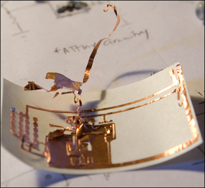
And here's where things get silly -- I was soldering the FR1 board, which I carelessly did not remove the double sided tape from. I accidentally set it on top of my vinyl cut circuit, and when I realized what had happened tried to pull the vinyl cut circuit off. This ended up pulling up some traces, so I tried to put it back, and quickly transfered it to the back of the copper backing to attempt to weed it. It sort of worked, except there was one thin trace that had gotten stuck on a different piece that basically broke when I tried to move it. Oops. So I made another vinyl cut board, but continued with my FR1 board so I could program it and debug it.
I programmed my board in assembly, where my 81 lines of code probably translates to 8 lines in C. Here I ran into problem after problem after problem -- first my board wouldn't initialize -- I'd get an initialization failed, rc=-1 error. I soldered a janky little wire from my V pin on the ISP header to my 4.7V line, and it worked from there...so I guess that pin does have to be powered after all. Then, after I programmed it, my output would PWM, but it'd be stuck at 50% duty cycle no matter what. Turns out "PINA" and "PORTA" do different things -- one is an input, the other an output. And then I'd be stuck at a constant 8% duty cycle no matter what I tried. I tried different ways of reading the ADC -- in both free-wheeling mode, and just reading it every loop, but it'd always be stuck at that 8% duty cycle. I then figured out that "LDI" loads the address, and not what the register is addressing, and the command I was looking for was "MOV" (which I originally thought didn't exist due to all the LD* commands). After that fix, everything worked well. Here's the link to my code: [link]
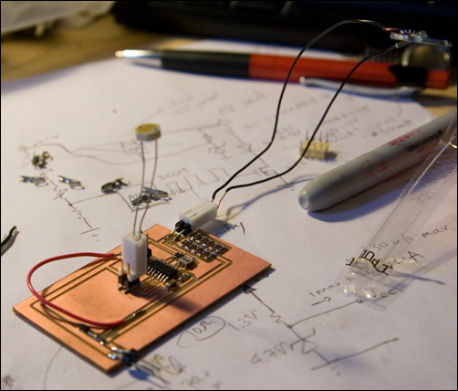
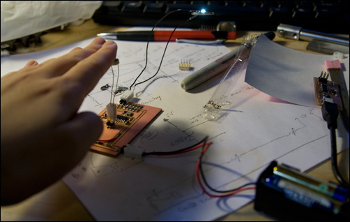
And the light does function exactly how I wanted it to! I'm not sure if you can actually tell that it's slightly brighter in the second picture, but it is. And if I shine a light directly on the photoresistor, it gets pretty dim. I'm thinking the next step is to map the ADC values into a db to generate something like an exponential function so that the brightness looks more linear.