Week Nine: Input Devices
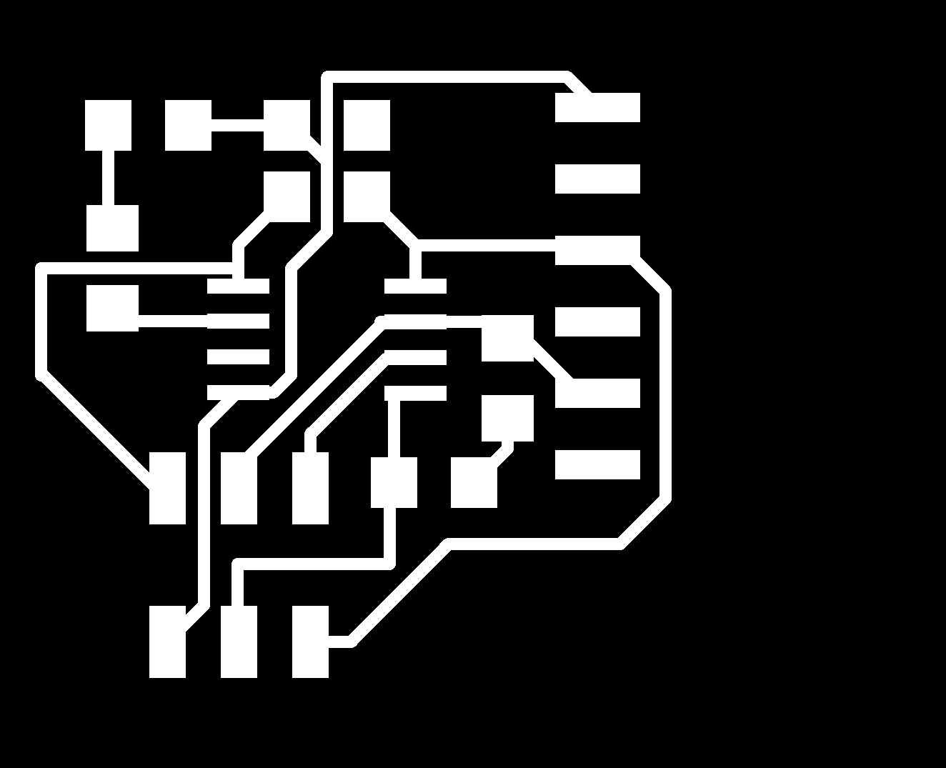
This week's assignment was to make an input device and read the input. I wanted to play with the idea of using an LED as a sensor -- when you reverse the voltage you apply on an LED, it effectively acts as a photodiode...so I wanted to test this out. I made a board with two LEDs, with the intention of making one drive itself but on the off chance that it was too slow I'd just have it drive the other. The gist of the routine is: apply a reverse voltage on the LED (control this via two pins -- pull the anode low and cathode high). Then, switch the cathode to a tri-state input, and either read off the value through an ADC or count how long it takes before it reaches a digital 0 (reading it through an ADC takes a few machine cycles, while counting it takes many many machine cycles). What happens is that the light charges up an internal parasitic capacitance, and that charge decay is what we're trying to measure. Here's the board I cut:

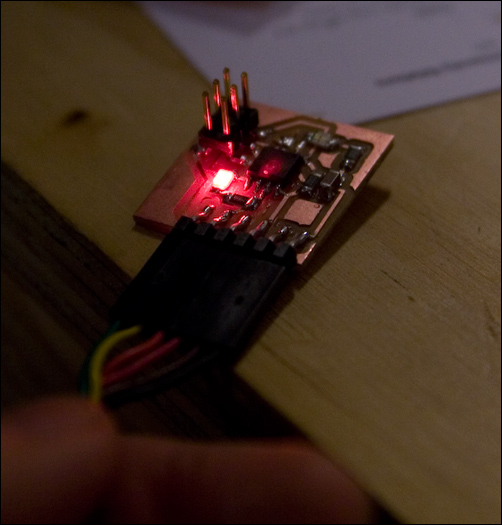
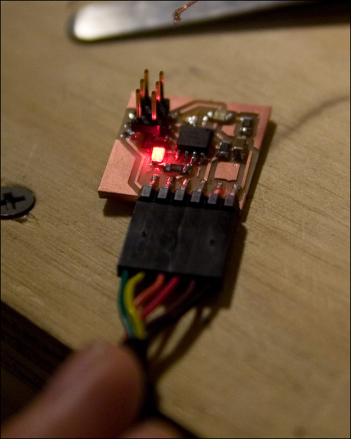
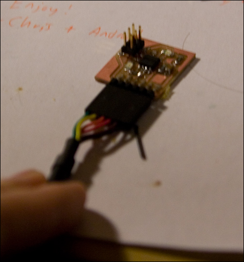
The milling and stuffing went as usual... but programming it took many many hours for reasons still unknown to me :( I first tried programming it in assembly, but for some reason it seemed like the ADC was not converting. Then I tried programming it in arduino, but got pretty much the same thing, it seemed. A few hours (and lots of frustration) later, I decided to reverse the output-only LED and make it input-only, and use my sensing LED as the output LED. This, for whatever reason, made things work. Also, later, when I ran the program again it seemed like it wasn't working, so I hooked up my scope to see what the signals looked like...and the moment I clipped my probe ground to board ground it started working again. I'm really not sure what caused this (possibly a finicky FTDI cable?). I tried to get photos of it in various light on my desk, but it's probably difficult to tell that it's actually dimming and then going to off in bright conditions:


If this worked the first time around I would've spent all that time getting this to work in assembly so I could use the LED as its own sensor with all the proper timings (versus sort of arbitrary "delay" values). I'm pretty sure there's some way of doing this such that you could do all your ADC conversions during the off bit of the duty cycle, probably via frequency modulation. I also would've mapped ADC values to some sort of exponential function so that its response seems more linear. But alas, spending a few hours on debugging took that time away... Anyway, I think with more time I'd like to make a reactive touch pad like this as well.