Week 2: Press fit construction kit
Design summary: Used SolidWorks to design a GIK press-fit part (or something approximating one). The slot width is parametric and so can be adjusted via one dimension change. Default value is 4 mm based on caliper measurement of the cardboard stock to around 4.2418 mm. Made a 3D assembly to demonstrate the fit geometry. Initially forgot the chamfer and made some sizing mistakes, so edited the part file and allowed those changes to propagate into the assembly. Also played with rendering.
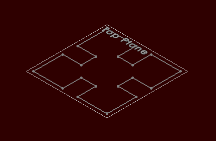
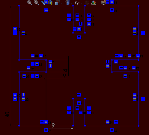
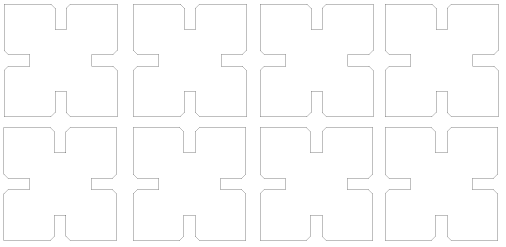
Make initial sketch.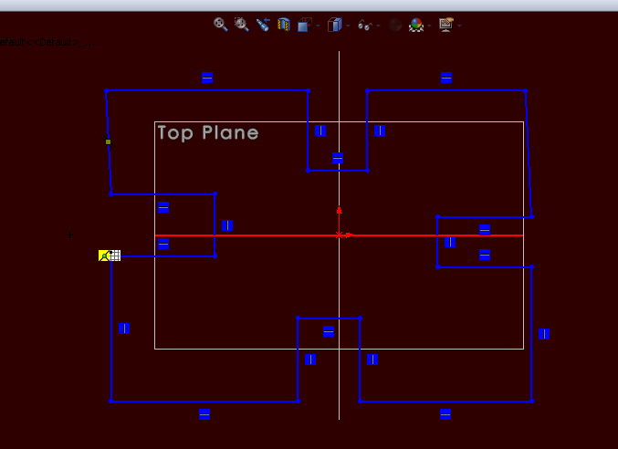
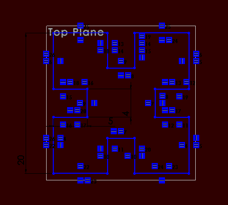
Add a bunch of constraints, in this case equality and vertical and horizontal. Then add the minimal number of dimensions which constrain the sketch fully.
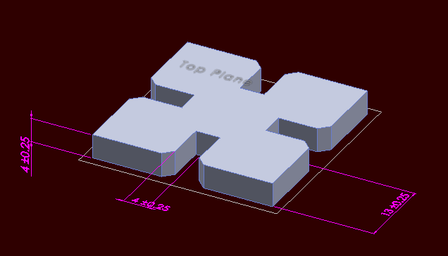
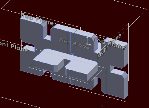
View sketch in 3D prior to extrusion.
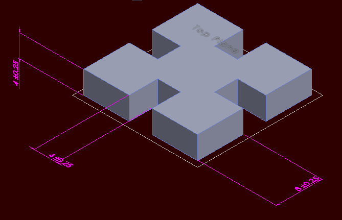
Extrude. Save as a part file.
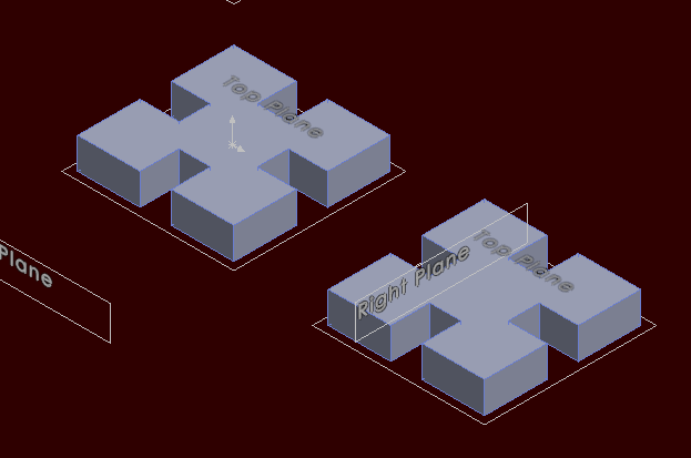
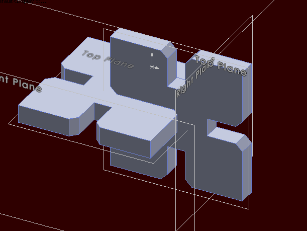
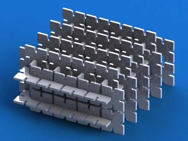
Switch to assembly. Place an object from the part file we just made. Copy the first component and move it. Rotate.
Oops, forgot chamfers. Adding these in the part file.
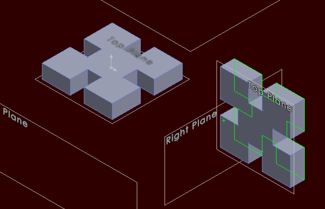
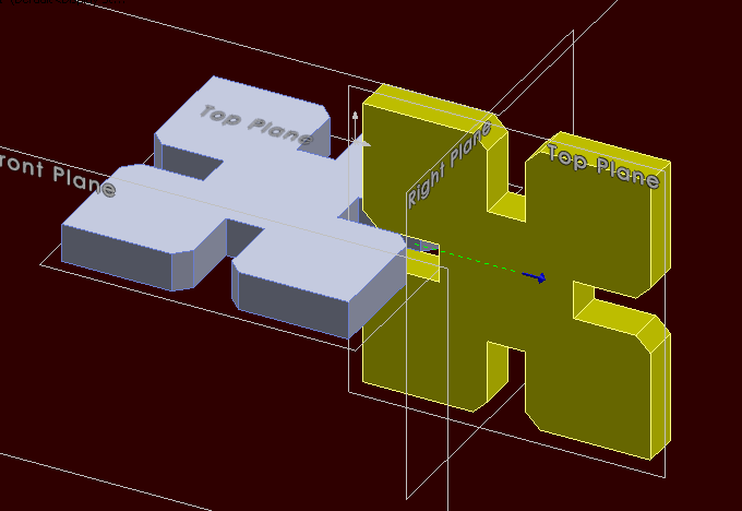
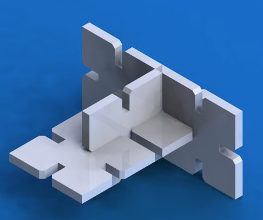
Switch back to assembly. Mate one corner point inside the slot to the corresponding corner point in the other piece. They snap together.
Explode components to view the geometry.
Save part as DXF.
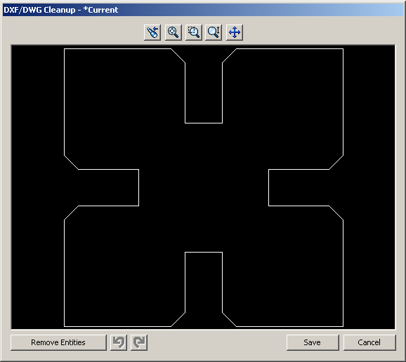
Edit as SVG in Illustrator.

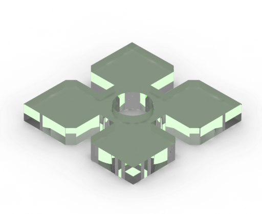
Play and render.
Ooops, slot is too deep. Will get a clash.
Edit part again.
Re-assemble and render in PhotoView 360. Looks like it should work!
Re-make laser cutter file for vector cuts in Illustrator using thinnest line width.
Tried out linear component arrays.
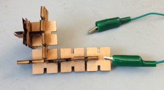
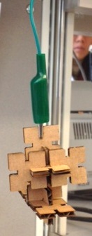
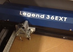
Fabrication: I did the Fab part on the Laser Cutter in the the Wyss. 75% speed, 40% power in two passes at 2500 Hz was enough for the pieces to fall through. Check after one pass. On that laser cutter, it's important to remember to turn on the filtration system which exhausts the machine, and the airline for the air assist, and to always watch the machine carefully. Some burnt-smelling vapor off-gassed from the cardboard for a few minutes afterwards.
The 4 mm slot width was a bit tight, but not too much to prevent my making a nice sea-horse thing.