Embedded programming: a FabSampler board
This week I made an AVR board (derived from numerous iterations with Charles towards a small-footprint sampling board for the EEG system) that samples two analog inputs and sends the sampled values over serial to a computer.
Schematic: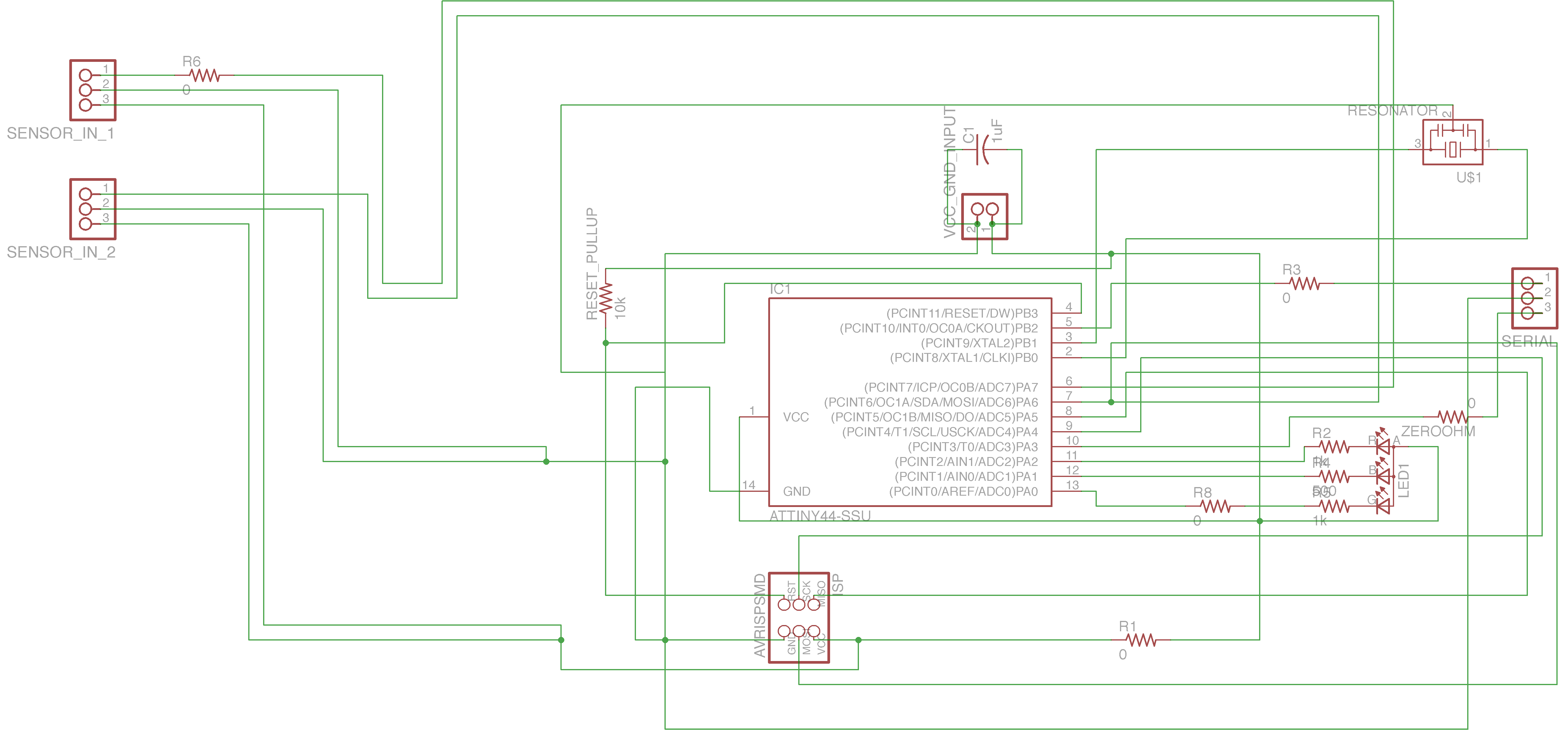
Board:
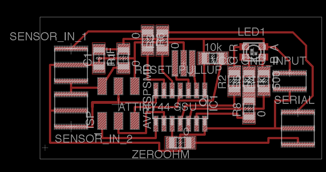
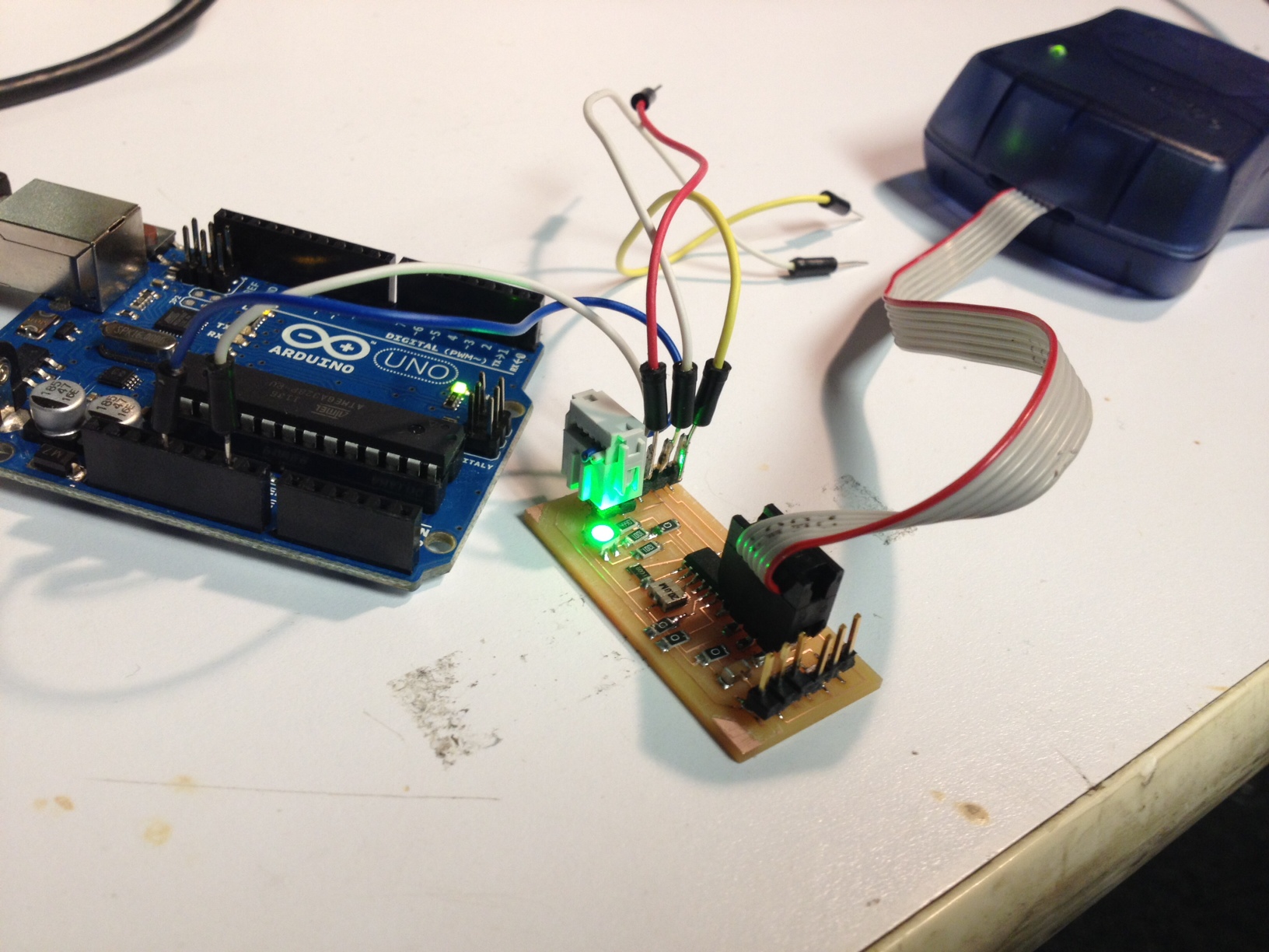
Image (the Arduino serving solely as a source of regulated 3.3V here to power the board):
Top (reduce end mill size in Fab Modules to make sure it cuts between all traces):
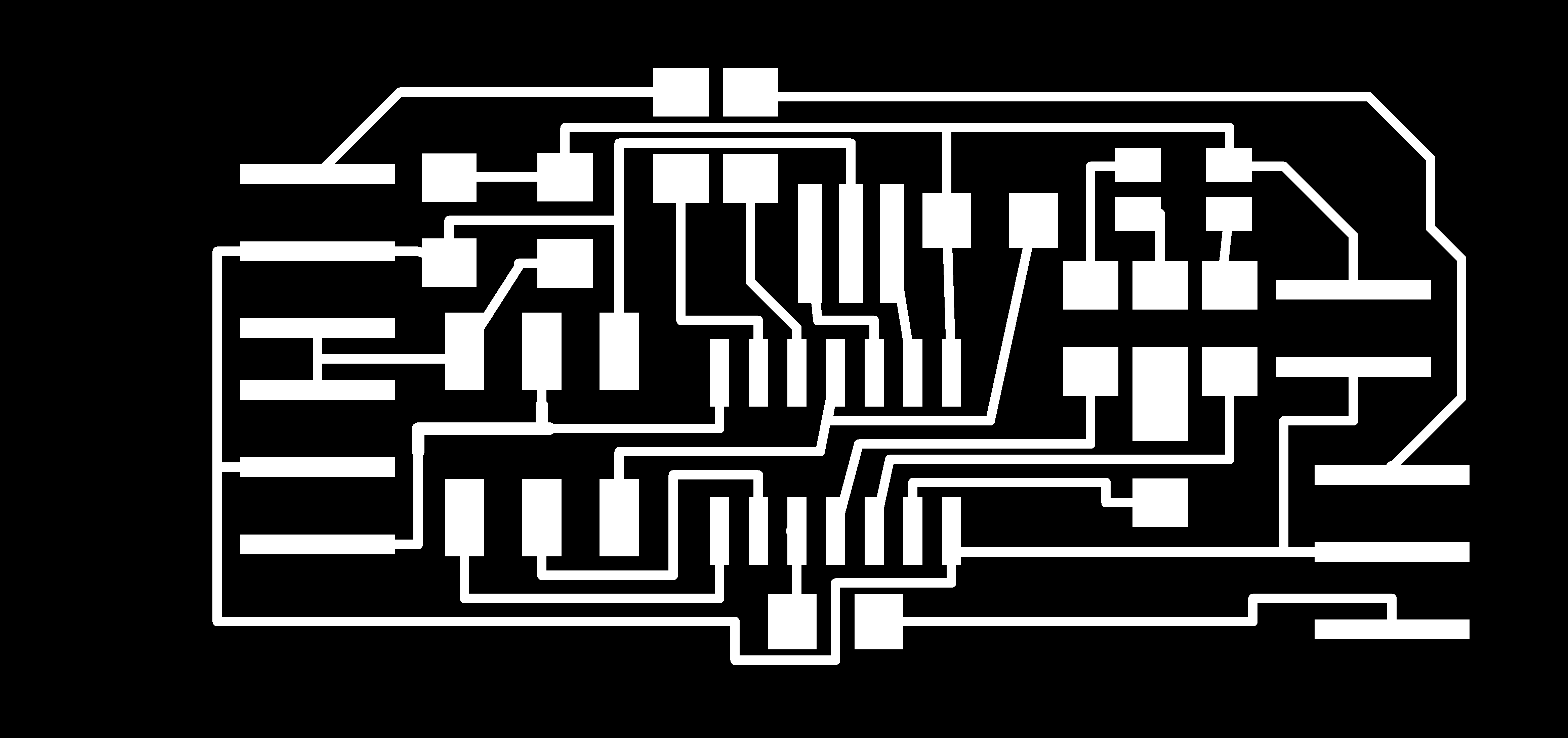
Interior:

Structure:
PB2 = serial Tx
PA3 = serial Rx
PA7 = sensor 1 input = port 6 on ATtiny = analog input 6 in arduino code
PA6 = sensor 2 input = port 7 on ATtiny = analog input 7 in arduino code
Then we have the programming header for an AVRISPmkII.
Finally we have a 3.3V input and a ground input.
The board supplies power and ground to the two sensor boards.
RGB part in Fab inventory is wrong by 180 degree rotation (2012-10-22)
Red LED pin = pin 12 on ATtiny schematic = pin 12 on Mellis HLT tutorial for arduino programming of AVR = pin 1 in arduino sketch
Green LED pin = pin13 on ATtiny = pin 0 in arduino sketch
Blue LED pin = pin 11 on ATtiny = pin 2 in arduino sketch
In my setup, an FTDI cable plugged into the computer's usb port (be sure to install the FTDI drivers) supplies power and ground to the board, powering an Arduino and using the Arduino to produce regulated a 3.3V supply (later version of the FabSampler will just include a regulator). The FTDI Rx and Tx pins are also connected to the Tx and Rx pins of the FabSampler board. The FabSampler provides its power and ground to subservient sensor boards, which send their analog signals into the sensor 1 and sensor 2 pins. According to the code below, the FabSampler reads those values, blinks the RGB LED in a purple color and sends the sensor value over serial to the computer.
Programming:
One way to program this is with Arduino code following this tutorial from David Mellis: http://hlt.media.mit.edu/?p=1695
Power the boards with 5V and ground and hook up an AVRISPmkII programmer. Then just program the board using the Arduino software.
Make sure to burn the correct fuse bits onto the board first -- here for a 20 MHz resonator: otherwise delay and other methods that use timing will be way off.
See David's diagram for mapping between arduino pins and avr pins.
I used the following program to grab samples from the inputs and send them over serial output:
#include \SoftwareSerial.h\
#define rxPin 8
#define txPin 3
#define led 1
#define led2 2
#define sensor1 7
#define sensor2 6
SoftwareSerial mySerial(rxPin, txPin); //rx, tx
// the Tx and Rx pins are 5 and 10 on the ATtiny which in Arduino code map to pin 8 and pin 3
// the setup routine runs once when you press reset:
void setup() {
pinMode(sensor1, INPUT);
pinMode(sensor2, INPUT);
pinMode(led, OUTPUT);
pinMode(led2, OUTPUT);
pinMode(rxPin, INPUT);
pinMode(txPin, OUTPUT);
mySerial.begin(9600);
}
// the loop routine runs over and over again forever:
void loop() {
digitalWrite(led, HIGH); // turn the LED on (HIGH is the voltage level)
digitalWrite(led2, HIGH); // turn the LED on (HIGH is the voltage level)
delay(2); // wait for 2 ms
digitalWrite(led, LOW); // turn the LED off by making the voltage LOW
digitalWrite(led2, LOW); // turn the LED on (HIGH is the voltage level)
delay(2); // wait for 2 ms
//mySerial.println("Sensor 1 value:");
mySerial.println(analogRead(sensor1));
//mySerial.println("Sensor 2 value:");
//mySerial.println(analogRead(sensor2));
//mySerial.println("");
//if (mySerial.available())
//mySerial.write(mySerial.read());
}
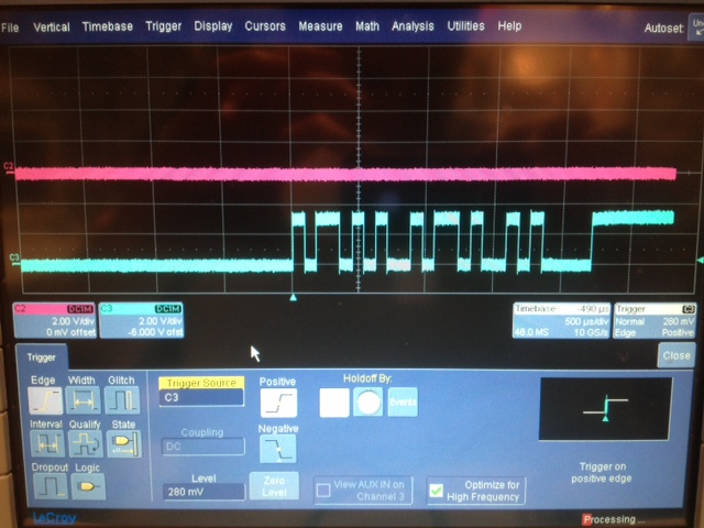
Initial debugging confirms the Tx pin is sending data:
When inputing a 1V, 1 Hz sine wave from a function generator (grabbing the terminal output and plotting in Matlab):
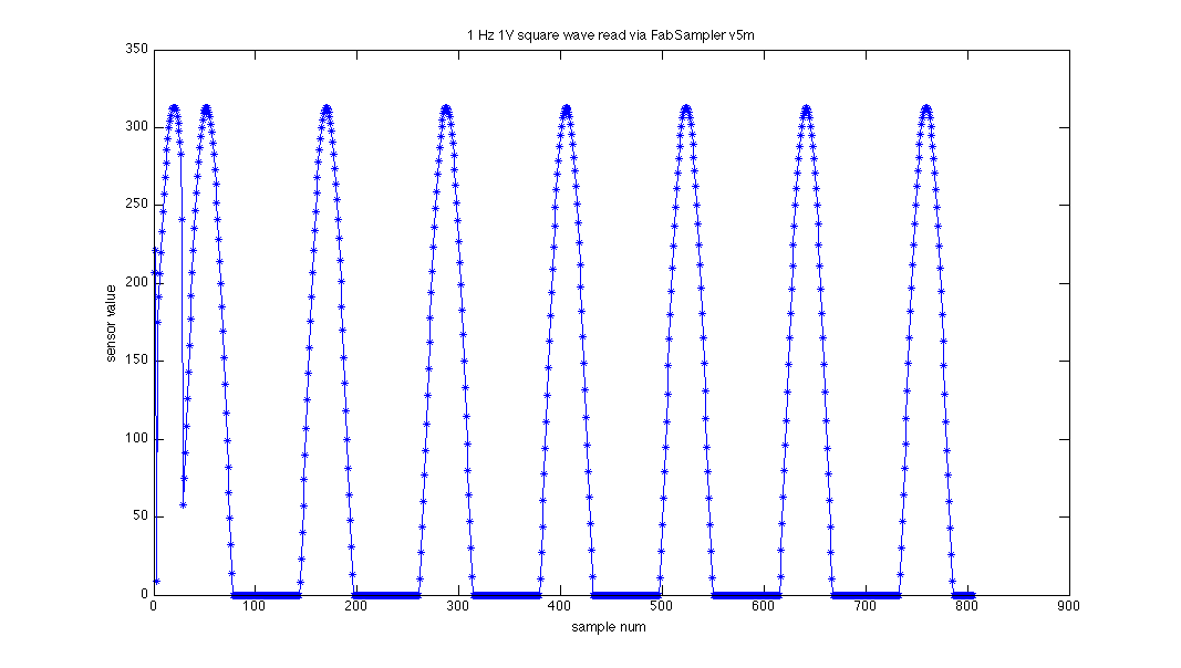
(note: the title of that plot is wrong -- it's a sine wave not a square wave)
Programming with Crosspack and C code also worked:
Adam-Marblestones-MacBook-Pro:desktop adammarblestone$ make -f FabSampler_v5m_echodebug.c.make
Adam-Marblestones-MacBook-Pro:desktop adammarblestone$ sudo make -f FabSampler_v5m_echodebug.c.make program-avrisp2-fuses
Adam-Marblestones-MacBook-Pro:desktop adammarblestone$ sudo make -f FabSampler_v5m_echodebug.c.make program-avrisp2
Links with examples on AVR programming:
C-program: http://academy.cba.mit.edu/classes/embedded_programming/hello.ftdi.44.echo.c
Make-file: http://academy.cba.mit.edu/classes/embedded_programming/hello.ftdi.44.echo.c.make
Programming work-flow using make-file: http://academy.cba.mit.edu/classes/embedded_programming/hello.ftdi.44.program.png
Note that you must power the board, e.g., through an FTDI cable in order to program it with an ISP.
For future reference, David Mellis has fantastic arduino sampling tricks in his sensors library:
http://dam.mellis.org/Mellis%20-%20Sensor%20Library%20for%20Arduino%20-%20Paper.pdf