how to make a fab-ISP
milling, soldering and programming
this task has three sections: milling the board, soldering in the components and programming the chip.


Part 1: Milling the Board using Modela
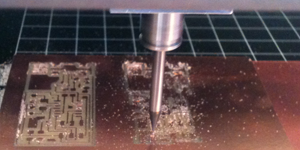
The machine used is called Modela. The fab modules can create .rml files to run the modela machine.
1. prepare the bed: 1 large sheet of substrate with double sided tape holding it down. target board to be cut above, secured with double sided tape.
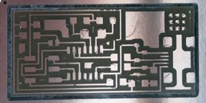
2. Upload a .png of the paths to be cut.
3. click 'make path'
4. check that the traces are set correctly in the image. Add or decrease traces as necessary.
5. press view on the modela machine to find the current x,y location
set x and y to correct point and click 'set xmin, ymin'
check that z depth is set to -0.1mm
6. For traces use 1/64 and to cut out the board use 1/32 drill bit
Debugging: If the bed isn't flat, then try a different area of the bed, which might be better stuck down, and adjust teh z depth. If the problem persisits, then replace the substrate.
Part 2: Soldering components onto circuit board
To solder a part:
1. heat the trace
2. Apply solder to the trace
3. place the component on top and heat the solder whilst holding down the component.
4. solder should flow onto the component.
When soldering I found it easiest to stick the board to my cutting mat with a piece of double sided tape, and then i only had to worry about 1 moving part. I found it easier to use the tweezers with my right (writing) hand, and to hold the soldering iron in my left.
Debugging: If there is too much solder on the components, then you can use copper braid to remove the excess