Electronics design
This weeks assignment was to learn electronics design. Though a number of programs are useful for this, my personal favorite and the one I have the most experience with is EAGLE. Designing a board in EAGLE is done in two steps; the schematic, in which you define connections between different components, and the board, on which you place the components and route physical traces.
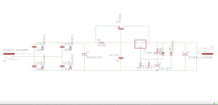
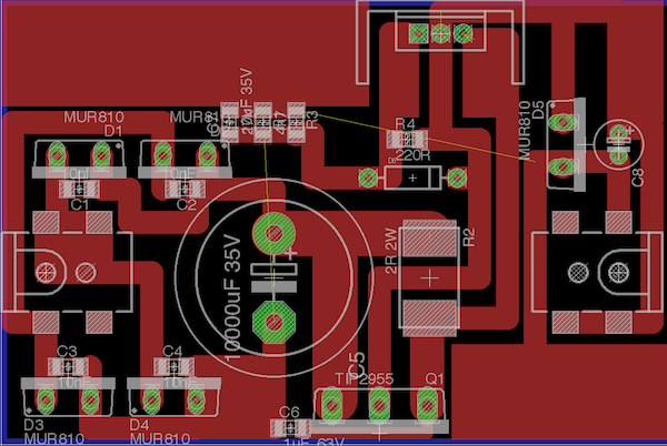
The schematic and board for the power supply of my amplifier
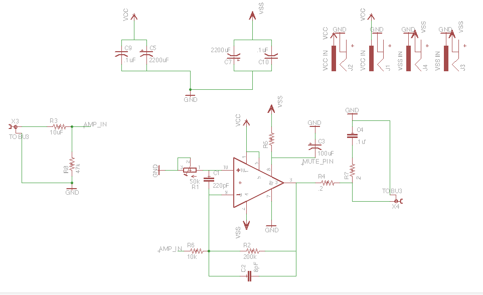
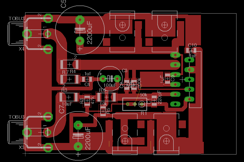
The schematic and board for the amplifier board
Our assignment was to create a development board for an AVR ATTiny44 microcontroller. However I've also been working on my final project and in the interest of getting a head start I decided to make a prototype of the amplifier that will be powering my sub.
The prototype consists of 3 boards, two power boards, which rectify, regulate, and smooth a 30V 60Hz input and output 30V DC, and an amplifier board, which takes an audio input (in this case just from my phone) and outputs a signal which drives a passive speaker.
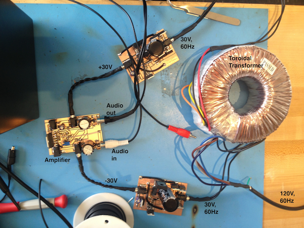
The 30V AC comes from two transformers which step down the 120V coming from the wall. Power cords in the US use black for hot, white for neutral, and green for ground, which I found out the hard way. Make sure you unplug everything from power before trying to adjust any wires so you avoid shocking yourself.
Both of my boards worked on the first try. The only complication I ran into was that on one board the heat sinks of two diodes touched and shorted power and ground, causing one of my traces to explode. Before powering up any board, use a voltmeter to ensure VCC, VSS, and GND are not connected.
After ensuring that none of my traces were shorting, I plugged everything in and pressed play on my phone.
Some notes:
When working with noise sensitive signals (ie audio signals) ground planes are your friend, right angles/current carrying traces are your enemy
When routing traces that will be carrying a lot of current, make sure they are as short and as thick as possible
You can route traces under other components (when milling, you can fit a 16mil trace under a 1206 component)
You can't route traces closer together than the size of your smallest endmill (check the path in the fab module)
Components that generate a lot of heat should be at the edges so they can be connected to a heat sink
Capacitors can hold charge even after power is removed (my amp would keep playing after being unplugged)
Through hole components can become surface mount components with wire cutters and pliers
Low pass filter power with a bypass cap (or several)
Traces that can't be easily routed can sometimes be connected with a wire
Check what pin the heat sink is connected to
Files
The schematic and board for the power supply of my amplifier
The schematic and board for the amplifier board
Our assignment was to create a development board for an AVR ATTiny44 microcontroller. However I've also been working on my final project and in the interest of getting a head start I decided to make a prototype of the amplifier that will be powering my sub.
The prototype consists of 3 boards, two power boards, which rectify, regulate, and smooth a 30V 60Hz input and output 30V DC, and an amplifier board, which takes an audio input (in this case just from my phone) and outputs a signal which drives a passive speaker.
The 30V AC comes from two transformers which step down the 120V coming from the wall. Power cords in the US use black for hot, white for neutral, and green for ground, which I found out the hard way. Make sure you unplug everything from power before trying to adjust any wires so you avoid shocking yourself.
Both of my boards worked on the first try. The only complication I ran into was that on one board the heat sinks of two diodes touched and shorted power and ground, causing one of my traces to explode. Before powering up any board, use a voltmeter to ensure VCC, VSS, and GND are not connected.
After ensuring that none of my traces were shorting, I plugged everything in and pressed play on my phone.
Some notes:
When working with noise sensitive signals (ie audio signals) ground planes are your friend, right angles/current carrying traces are your enemy
When routing traces that will be carrying a lot of current, make sure they are as short and as thick as possible
You can route traces under other components (when milling, you can fit a 16mil trace under a 1206 component)
You can't route traces closer together than the size of your smallest endmill (check the path in the fab module)
Components that generate a lot of heat should be at the edges so they can be connected to a heat sink
Capacitors can hold charge even after power is removed (my amp would keep playing after being unplugged)
Through hole components can become surface mount components with wire cutters and pliers
Low pass filter power with a bypass cap (or several)
Traces that can't be easily routed can sometimes be connected with a wire
Check what pin the heat sink is connected to
Files