Embedded programming
Coming off a week where my project was a disaster, I was excited for embedded programming. I've worked with AVR microcontrollers many times in the past, and was confident I'd be able to make something work. I decided to make a thermometer, but rather than display the temperature, it would display one of four adjectives describing the temperature, hot, warm, cool, or cold. Each word would be lit up with different colored LEDs driven by N channel MOSFETs. I wanted to be able to control the brightness by PWMing the FETs, so that in the future I could use the intensity of the light to display even more information.
I designed my boards in eagle. One contained just the LEDs, and one contained the AVR, FETs, thermistor, USB as a power source, and everything else needed to make things work. I gave the AVR board a header to supply power and the drain of each FET to the LED board.
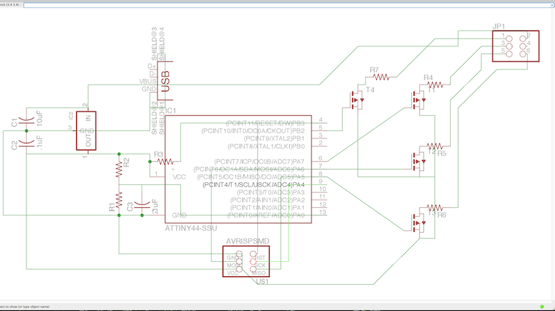
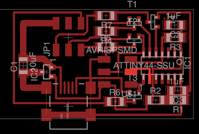
The schematic and board containing the AVR
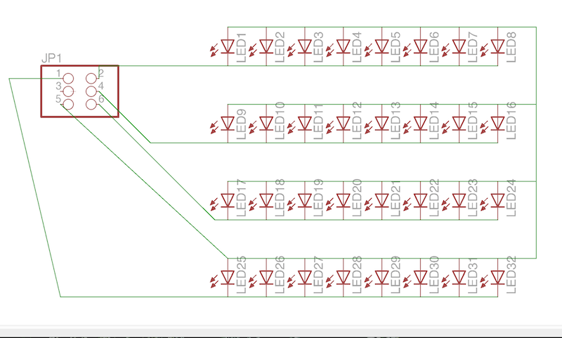
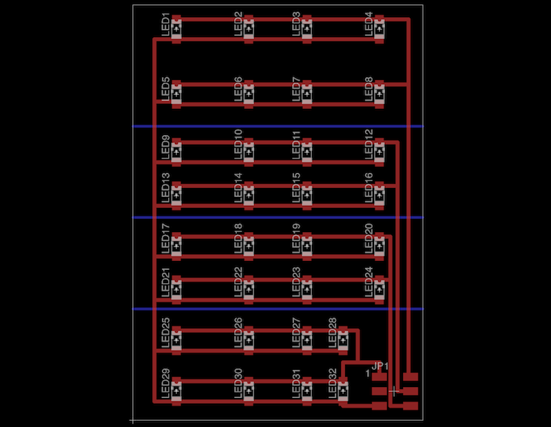
The schematic and board containing the LEDs
After milling and stuffing my board, I realized I had a short between power and ground. I found out that I had routed traces under the USB jack, and that they were touching the casing, which was connected to ground. Covering the bottom of the casing in electrical tape fixed this problem. Finally I was ready to program my board.
The first step was to install all of the necessary software on my computer, including avr-dude, avr-gcc, make, and more. Fortunately everything I needed could be installed in one go, by downloading and installing crosspack.
Now I was ready to program my board. Luckily I had some old code to work with. First off, a Makefile, which translates commands typed in the terminal, such as make, or make program, into commands that compile and program your board. Next I had to write the actual code that the AVR runs. Since my board was pretty simple, there were only a few functions I needed to write. First, I had to write a getTemperature function, which would read the voltage on one of the pins of the thermistor, and return a temperature. The math to translate the voltage to a temperature is kind of complicated for an AVR, so I wrote some python code to create a lookup table for me to get temperatures from voltage readings. Reading the voltage is pretty simple, but can be confusing if you've never done it before. The ATTiny44 has pins that can function as analog to digital converters, which return a 10 bit number proportional to the voltage on the desired pin. The default setting is to set the range from 0-Vcc, but this can be changed. Reading a pin is accomplished by setting and reading certain registers (ADCSRA, ADMUX, and ADCW) in the AVR (for more information, read the datasheet).
Another function I had to write was the setPWM function, which takes a pin and a duty cycle, and sets the appropriate pin to PWM with the appropriate duty cycle. The intention of this function was to drive LEDs. Similarly to reading the ADC, all of this is accomplished by setting certain registers in the AVR. The only way to really learn about these registers and how to configure them properly is to spend a lot of time with the datasheet.
Though I had success programming my board, at some point something stopped working. I was unable to do the most basic turning pins on and off, even when I replaced the board. I redid the board, and stuffed it minus the FETs. It worked at first, but once I placed the FETs, I couldn't turn pins on and off anymore, even after I took them off, though I was able to program it throughout. Hopefully someone can help me out, so I can rebuild my board and make it work.
I know I didn't go into very much detail about the inner workings of my code/AVR. If you read my code, and look on with the data sheet as you do so, you should be able to figure everything out, I commented as best I could. I think most of it works, but since I was having what I'm pretty sure were hardware problems, I wasn't able to fully test everything.
I designed my boards in eagle. One contained just the LEDs, and one contained the AVR, FETs, thermistor, USB as a power source, and everything else needed to make things work. I gave the AVR board a header to supply power and the drain of each FET to the LED board.
The schematic and board containing the AVR
The schematic and board containing the LEDs
After milling and stuffing my board, I realized I had a short between power and ground. I found out that I had routed traces under the USB jack, and that they were touching the casing, which was connected to ground. Covering the bottom of the casing in electrical tape fixed this problem. Finally I was ready to program my board.
The first step was to install all of the necessary software on my computer, including avr-dude, avr-gcc, make, and more. Fortunately everything I needed could be installed in one go, by downloading and installing crosspack.
Now I was ready to program my board. Luckily I had some old code to work with. First off, a Makefile, which translates commands typed in the terminal, such as make, or make program, into commands that compile and program your board. Next I had to write the actual code that the AVR runs. Since my board was pretty simple, there were only a few functions I needed to write. First, I had to write a getTemperature function, which would read the voltage on one of the pins of the thermistor, and return a temperature. The math to translate the voltage to a temperature is kind of complicated for an AVR, so I wrote some python code to create a lookup table for me to get temperatures from voltage readings. Reading the voltage is pretty simple, but can be confusing if you've never done it before. The ATTiny44 has pins that can function as analog to digital converters, which return a 10 bit number proportional to the voltage on the desired pin. The default setting is to set the range from 0-Vcc, but this can be changed. Reading a pin is accomplished by setting and reading certain registers (ADCSRA, ADMUX, and ADCW) in the AVR (for more information, read the datasheet).
Another function I had to write was the setPWM function, which takes a pin and a duty cycle, and sets the appropriate pin to PWM with the appropriate duty cycle. The intention of this function was to drive LEDs. Similarly to reading the ADC, all of this is accomplished by setting certain registers in the AVR. The only way to really learn about these registers and how to configure them properly is to spend a lot of time with the datasheet.
Though I had success programming my board, at some point something stopped working. I was unable to do the most basic turning pins on and off, even when I replaced the board. I redid the board, and stuffed it minus the FETs. It worked at first, but once I placed the FETs, I couldn't turn pins on and off anymore, even after I took them off, though I was able to program it throughout. Hopefully someone can help me out, so I can rebuild my board and make it work.
I know I didn't go into very much detail about the inner workings of my code/AVR. If you read my code, and look on with the data sheet as you do so, you should be able to figure everything out, I commented as best I could. I think most of it works, but since I was having what I'm pretty sure were hardware problems, I wasn't able to fully test everything.