Input devices
This was another week focused on electronics, specifically, input devices. Examples of input devices include microphones, touch sensors, light sensors, really anything that measures something about the outside world. A few weeks ago I had tried to make a thermometer using a thermistor and and AVR, but was never able to make it work. This week, I tried again, and was ultimately able to make it work.
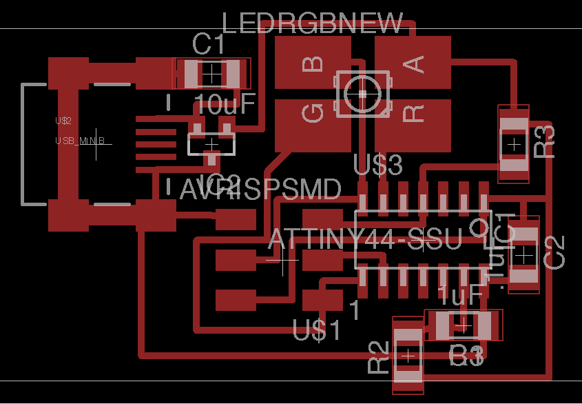
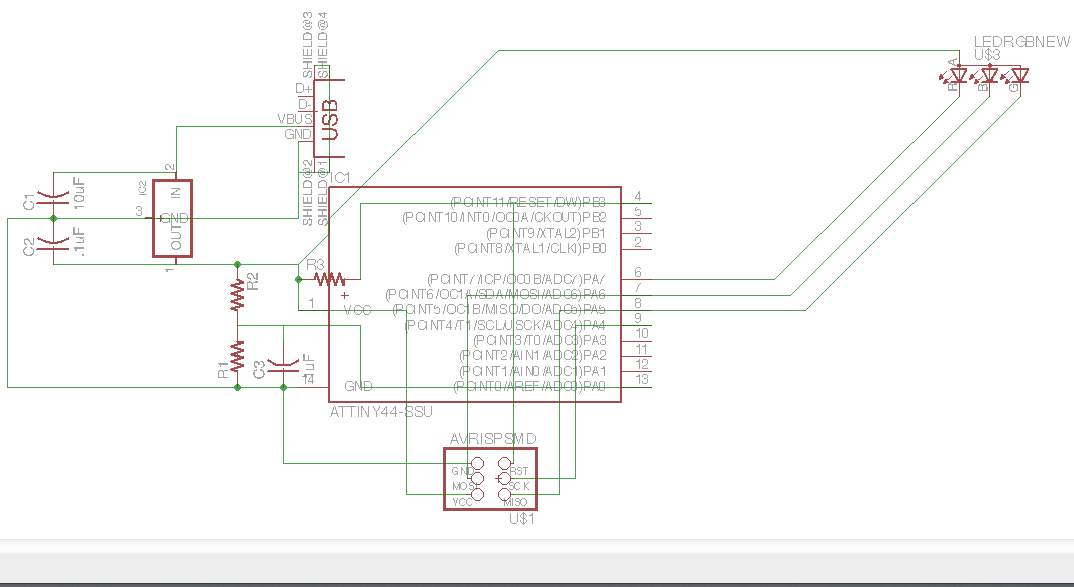
Due to the very strange behavior of my board last time, I decided to design an entirely new board. Instead of using four arrays of LEDs to light up words, I decided to use an RGB LED to display the temperature. Again, I measured temperature using a 10kOhm thermistor in series with a 10kOhm resistor to make a voltage divider, and used an ADC pin on the AVR to measure the voltage after the thermistor. The math to convert this voltage to a temperature was too complicated for an AVR to handle, so last week I wrote a python script to create a lookup table that mapped ADC values to temperatures. As I eventually figured out, this was the reason my original board didn't work; the size of the table was too great for the AVR. Suprisingly, I didn't get an error when trying to program the AVR, so it took me a long time to discover that this was the problem.
My first attempt to fix this problem was to shrink the size of the table by half, and sacrifice the precision of my temperature readings. My program loaded and things seemed to be working as I could PWM the RGB LED, something I was unable to do last time. However I had no way of telling if my temperature readings were accurate or not. To do this I needed to write code that allowed me to set the color of the RGB LED. I wrote a function called displayColor, which takes a wavelength and sets the output of the LED to display light of approximately that wavelength. RGB LEDs use the additive color model (thank you wikipedia), so the color we see is a weighted (by brightness) average of the wavelengths of the red, green, and blue components. My approach was to divide wavelengths into four categories, red-green, green-red, green-blue, and blue-green, and to create my best approximation of the wavelengths by guessing intensities until the approximation was roughly equal to the wavelength I desired. After a little work, I had this code working, and I could display whatever wavelength I wanted. Now that I was able to convey some information from my ADC readings, I found out that my temperature lookup table wasn't working, but my ADC readings were. I decided ultimately to just set the LED to display a wavelength equal to the ADC reading, as the readings will increase with temperature, and are generally in the range of 472-621, the spectrum that the LED can display. This means that the LED will display blue for very cold temperatures, and gradually increase in wavelength as temperatures get hotter. I've had my thermometer in my freezer for the last few hours, and it should be pretty cold. Here's a video of it warming up (with some help from my hot plate to speed things up):
Eagle files and firmware