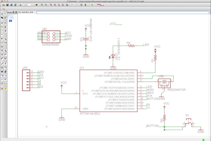
Following the tutorial on Eagle, I started to play with it. I have added Fab and Sparkfun
libraries for the components. The program is very easy to use despite being different from conventional cad programs. Move, rotate etc. commands slightly different. There are two files connected to each other; schema file, where you create your circuit with compoents in a symbolic manner and the board file, where actual dimensions and traces are created.
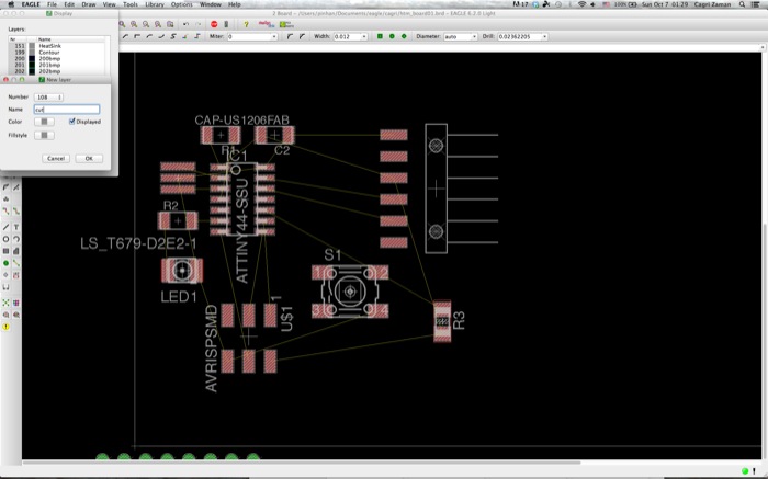
This is the initial layout of my board. I decided to manipulate this geometry and rotated the 6-pin header 45 degrees.
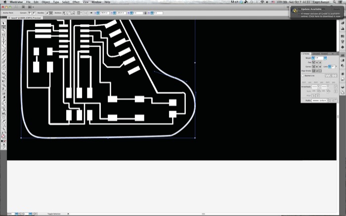
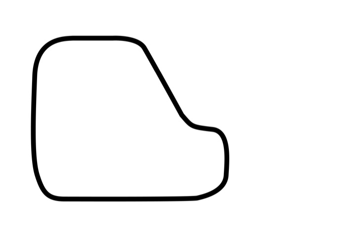
Unfortunately, just after I export the traces, the Eagle program crashed and I lost the cut out paths I have created. Instead starting from scratch I used Illustrator to draw the outline. It is much easier to use Illustrator for this purpose!
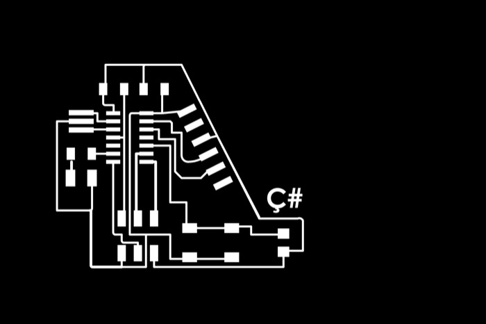
Final board with my inital letter.
Cut-out path
I sent the files to modela using fab modules. In this step I only follow the steps and make no changes at all.
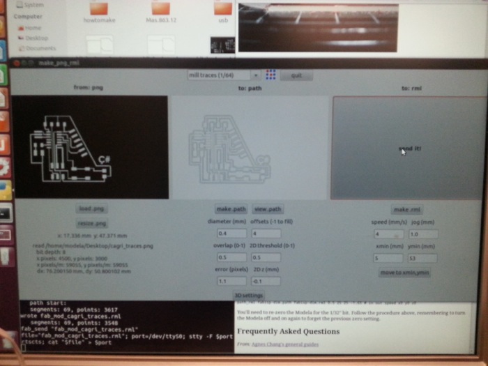
Milling the traces
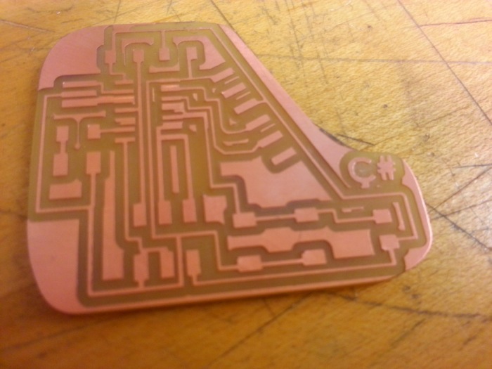
Cutting out the board
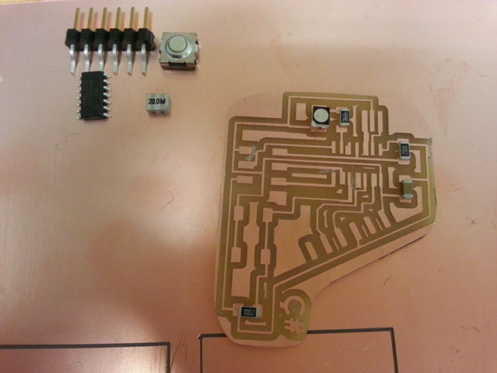
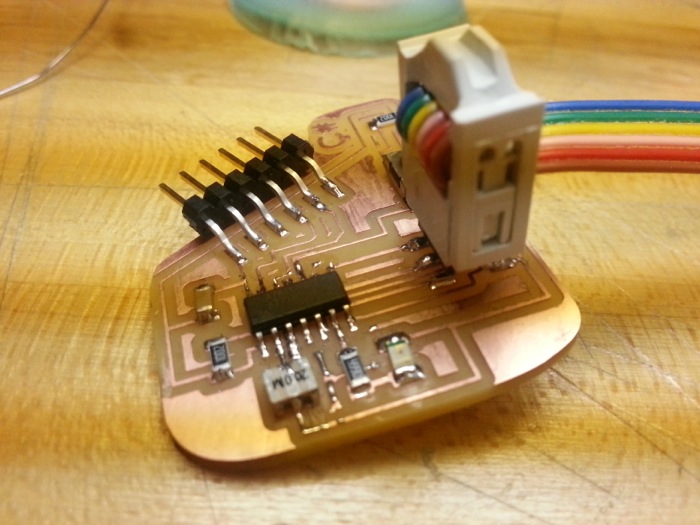
The board before stuffing.
Stuffing the board.
I have completed making the board with one LED and Button. Afterwards I wanted to check if it works.
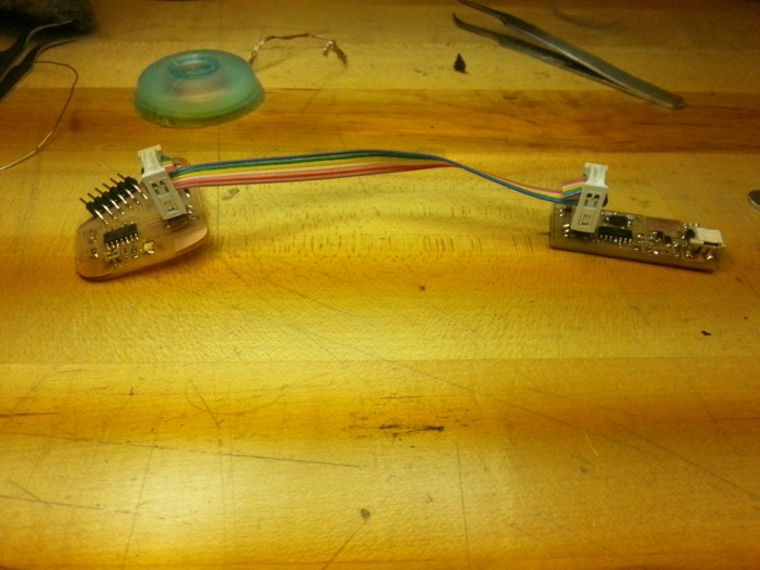
Infortunately, my older work, tinyUsb did not work and I had to use AVRMkII to program my board.
First I uploaded the hello world code into my board, and read "CaCa" from serial port. (I though it supposed to say Hello :)
I followed one of the older codes for button and led to upload my board. In my first trial it did not work. After I checked the codes, I saw the ports and pins were different then the ones I used. I fixed the lines and it worked.
I decided to create a S.O.S signal with the led, I have written the code in order to manage it. 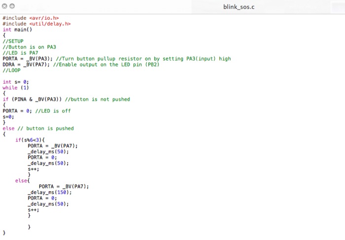
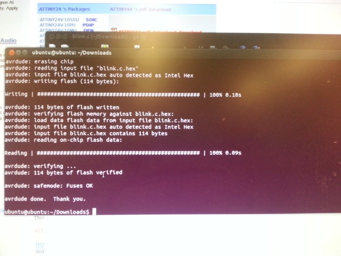
Uploading the code to board.
Sample Files
Blink SOS Code
Make FIle
Traces
Cut-out
Back