Press-fit Kit
assignment
design,
make, and document a press-fit construction kit
my goal
I decided
to create parts to teach my two-year-old daughter about modularity.
so, I
have created two designs:
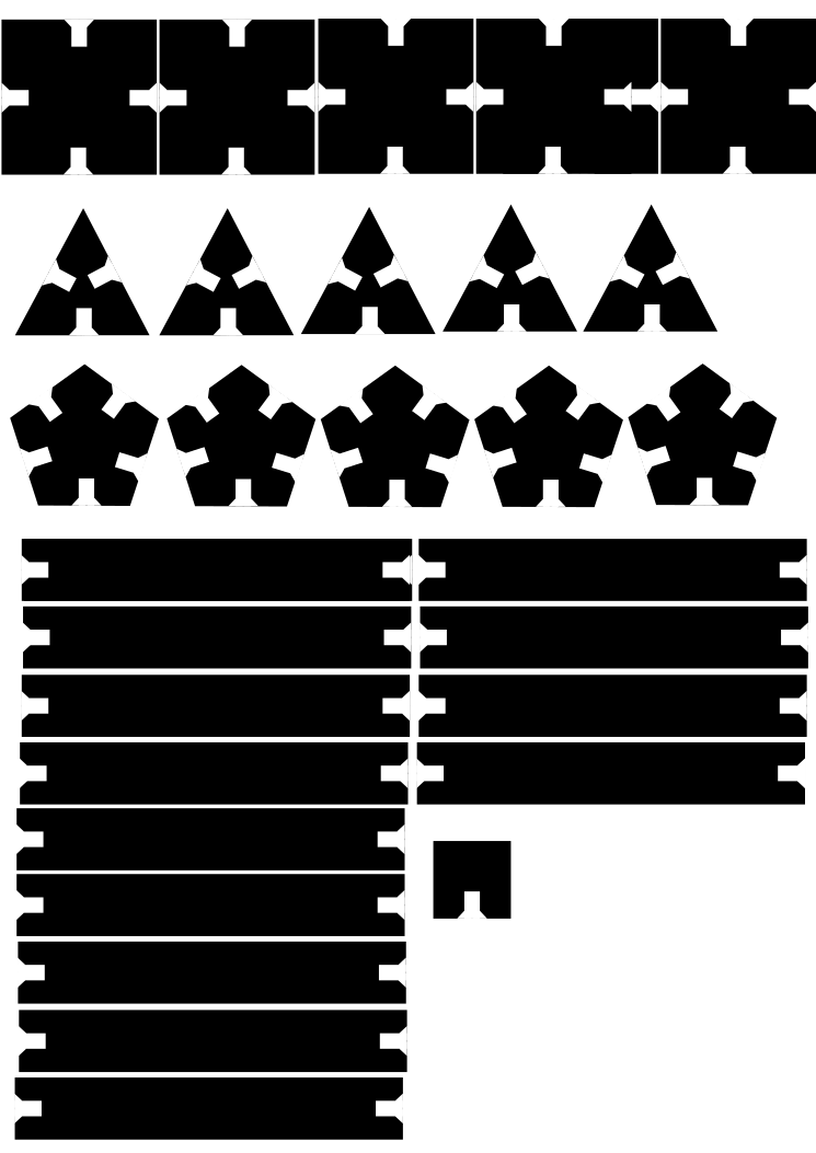
design a: where
modules are standard (rectangles) but connectors change (triangle, square, pentagon)
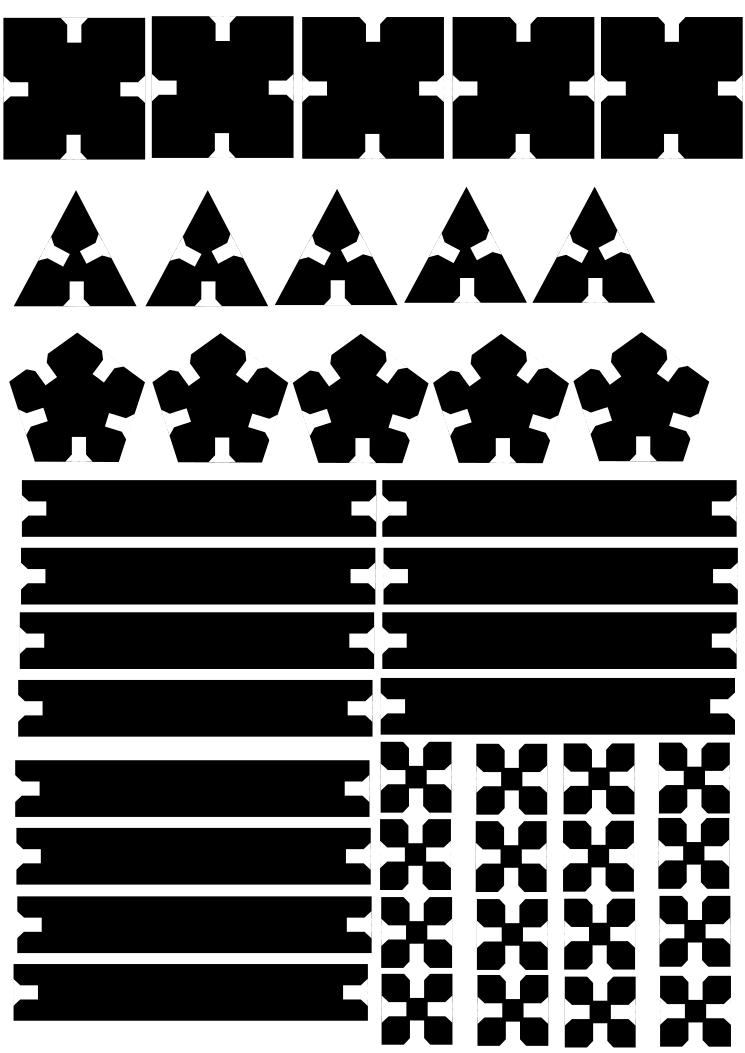
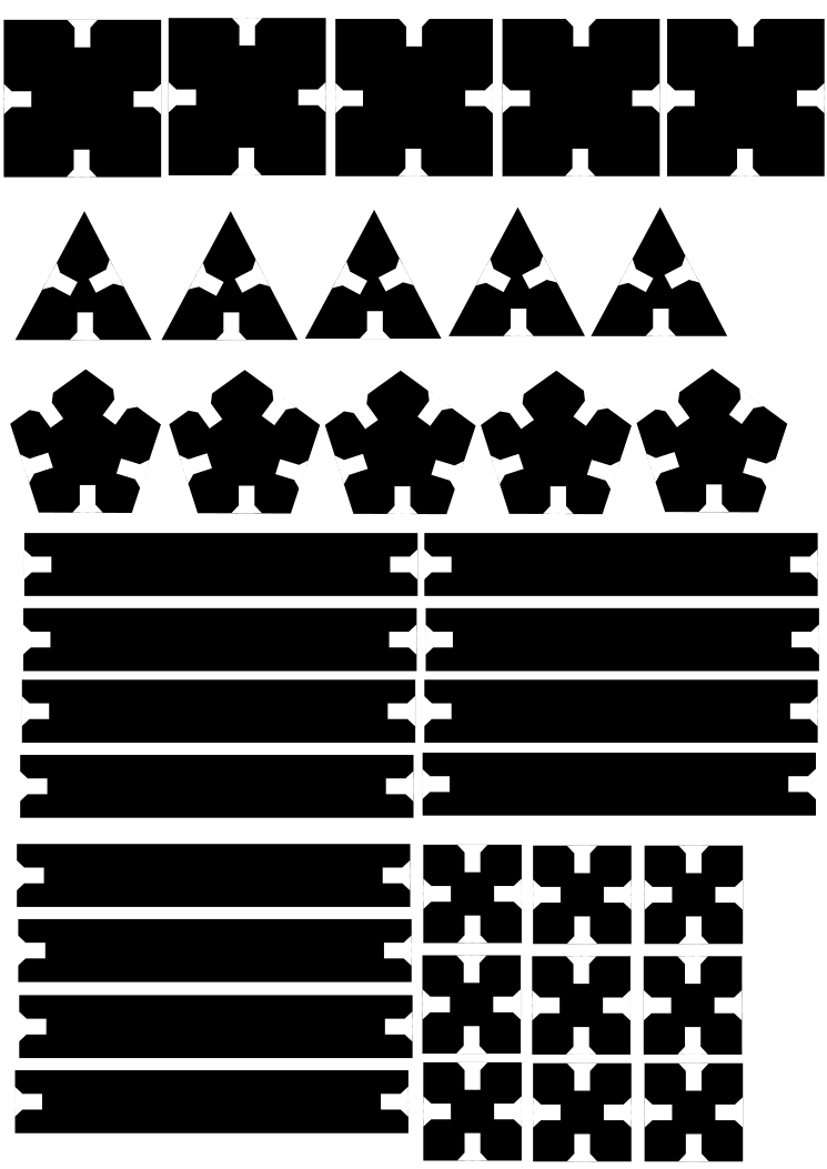
design b: where
connectors are standard (square) but module change (square, triangle, pentagon)
design a
|
|
|


with
design a, I want to demonstrate to her how simply changing connectors changes
the architecture
|
|
|


design b
|
|
|


with
design b, I want to demonstrate to her how changing modules while keeping
connectors unchanged changes the level of complexity without changing the
architecture
|
|

final frontier
the final
frontier, of course, is to show how
very complex shapes (too complex to survive) have to have both complex modules
and connectors
|
|

process notes
i started this project as a complete novice (well, apart from
being an engineer who knows principles of engineering drawing, but that is not
necessary). most of my effort went into knowing
learning vector drawing software (inkscape), fab
tools, laser cutter, and mercurial (for version control).
i had to overcome three problems:
a)
when i converted .png to
epilog file for laser cutter the first time, the lines got a bit jagged. i later learned that i had to set the resolution right to avoid that
b) when path was created from the epilog
file, i realized that i had
placed the pieces too close to each other, so in some cases lines separating
two pieces was absent. this problem was fixed by
re-spacing the shapes
c)
through trial-and-error, i also realized something
i should have in the first place: the connectors had
to be large enough that when two modules are connected to a single connector
they don’t collide
i tried one shape of each type before replicating them. below are the progression of files i
created.
project files