Week 9 – Input
Devices
Knockdown Warning
Indicator.
Measure something: Add a
sensor to a board, and measure something with it.

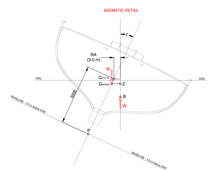
This week’s plan is to build a device that warns of the
potential of a knockdown – the process by which an over-canvassed ship is
lain over on her beam-ends. The
potential for sinking at this point is high, so it is an event to be
avoided. As the reading of squall
curves (from vessel stability booklets) is a skill rarely practiced these days,
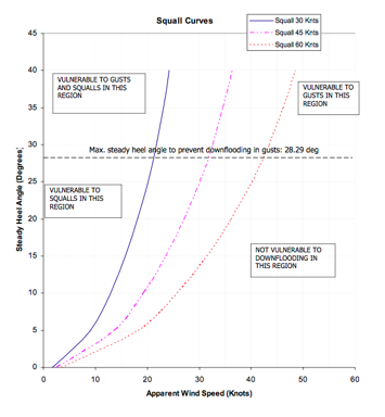
such a device has merit. A squall
curve diagram generally indicates the maximum angle of heel recommended for a
given wind velocity, and the potential for gusts.
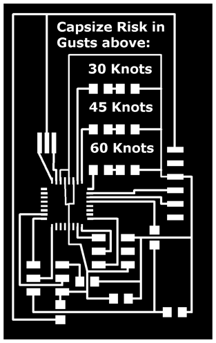
At a basic level, assuming a prevailing wind of 25 knots
(beaufort force 6), this device will measure heel
(inclination) and indicate the level of gust that would present a knockdown
risk based on that angle of heel, by flashing a LED for either 60 knots, 45
knots or 30 knots.
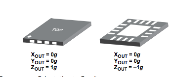
I based the design around an accelerometer, with the
plan being to trial more than one.
The sort we have in stock is a single axis, but Lindy had an ADXL335,
3-axis (one of the new ones, and it was around this that I designed the
circuit. With three axis inputs,
and three LED outputs, I needed to use the ATMega88 – new for me.
Data sheets for ADXL335
and ATMega88.
Excellent resources for using the ADXL335:
http://www.electronicsblog.net/simple-angle-meter-using-adxl335-accelerometer-arduino/
http://www.evilmadscientist.com/2007/using-an-adxl330-accelerometer-with-an-avr-microcontroller/
Here’s my schematic.
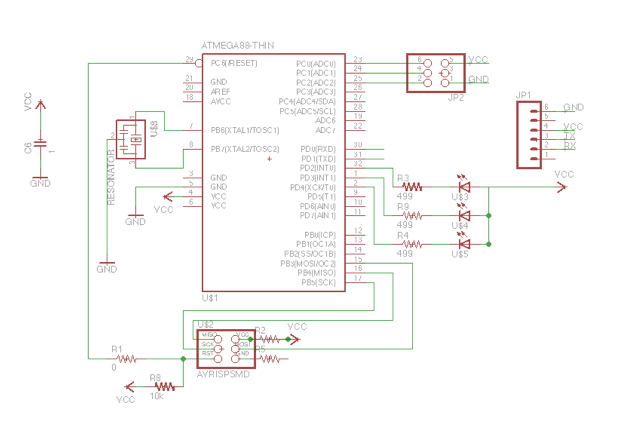
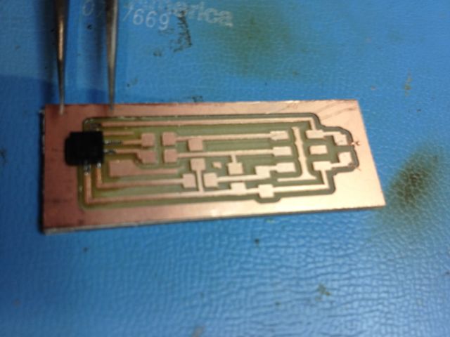
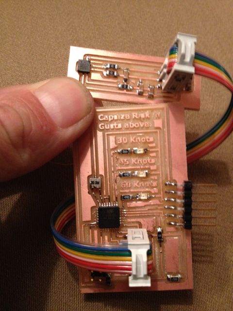
I
designed the circuit so that the accelerometer resided on a separate board with
three passive lo-pass filters that would connect to the main board via a 2x3
pin arrangement. I set the board up
this way so that I could experiment with several accelerometers, hoping to
ultimately build my own using a flexure.
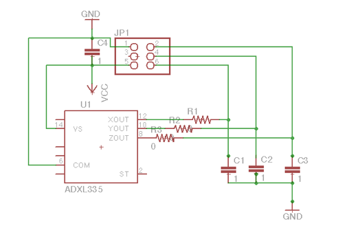
The
ADXL335 has resistors built in resistors so technically I don’t need the ones
in the above diagram, and they are zero ohm. I included them on the advice of a
former technical director at RIM who said she always made provision for them,
so she could tweak the filter later if necessary.
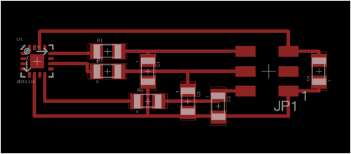
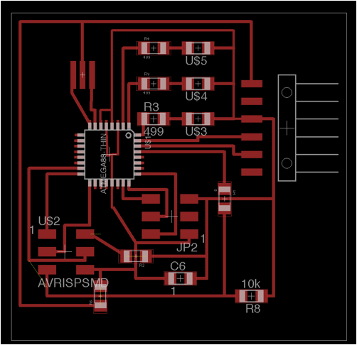
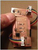
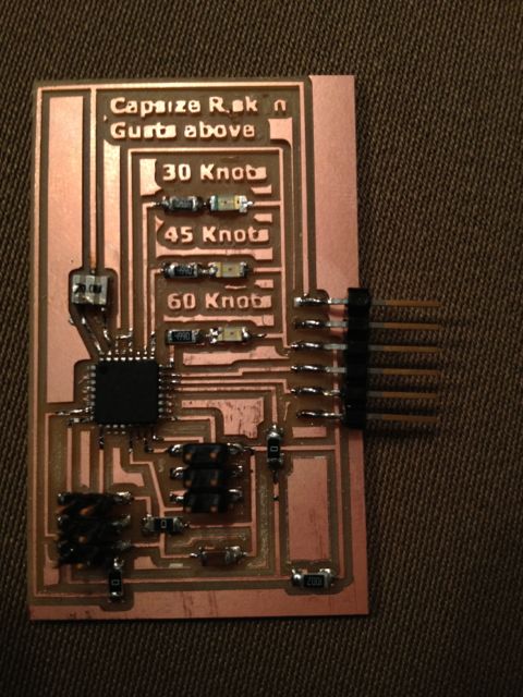
I
spread the layout a little to fit in some text on the main board
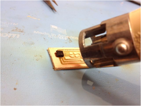
The ADXL335 is tiny, with the pads entirely ventral.
Neil’s advice was to solder the traces underneath, then use the heat gun.
The ATMega was a challenge, especially as I had led some of the traces under the chip.
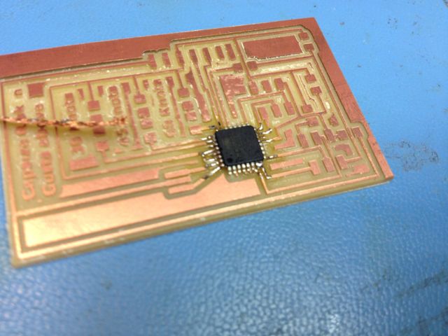
Apart from that, the boards were pretty straightforward:
Alas, I could not get the AVRISP to recognize the board. I troubleshot every connection on the board, and they all seem to work. The easiest component to suspect is the ATMega – maybe I cooked it while soldering, or maybe I shorted it out at some stage.
I may go one level simpler, and use a ATTiny44 and the one axis accelerometer, just to get the code working on a board.
For coming weeks, (once I get this working) I’d like to add an input from an anemometer (wind indicator) and have the device interpret both inputs against the squall curves. I may combine this with Output devices.