Week 11 – Output
Devices
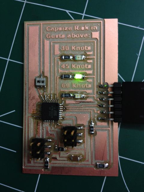
Knockdown Warning
Indicator (Redux)
Add an output device to a microcontroller board and program
it to do something.

This week I continued developing a device that warns of
the potential of a knockdown – the process by which an over-canvassed
sailing ship is lain over on her beam-ends during a squall. The potential for sinking at this point
is high, especially if there are hatches open on the leeward side, so it is an
event to be avoided. As the reading
of squall curves (from vessel stability booklets) is a skill rarely practiced
these days, such a device has merit.
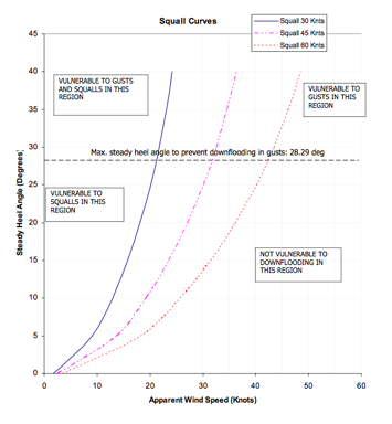
A squall curve diagram generally indicates the maximum angle of heel
recommended for a given wind velocity, and the potential for gusts. The 210’ tall ship Concordia sank in 2010 in such an event.
I came up with the concept during input devices week,
and am developing it further for a final project. Much of this information is a repeat.
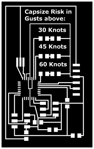
At a basic level, assuming a prevailing wind of 25 knots
(beaufort force 6), this device will measure heel
(inclination) and indicate the level of gust that would present a knockdown
risk based on that angle of heel, by flashing a LED for either 60 knots, 45
knots or 30 knots.
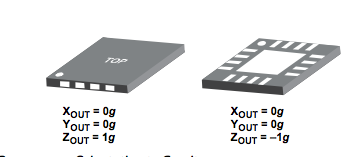
I based the design around an accelerometer, with the
plan being to trial more than one.
The sort we have in stock is a single axis, but Lindy had an ADXL335,
3-axis (one of the new ones, and it was around this that I designed the circuit. With three axis inputs, and three LED
outputs, I needed to use the ATMega88 – new for me.
Data sheets for ADXL335
and ATMega88.
Excellent resources for using the ADXL335:
http://www.electronicsblog.net/simple-angle-meter-using-adxl335-accelerometer-arduino/
http://www.evilmadscientist.com/2007/using-an-adxl330-accelerometer-with-an-avr-microcontroller/
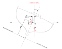
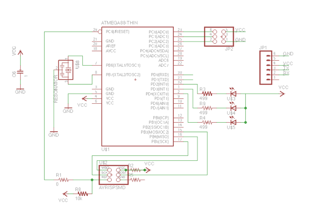
Here’s my schematic.
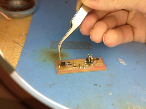
I
designed the circuit so that the accelerometer resided on a separate board with
three passive lo-pass filters that would connect to the main board via a 2x3
pin arrangement. I set the board up
this way so that I could experiment with several accelerometers, hoping to
ultimately build my own using a flexure.
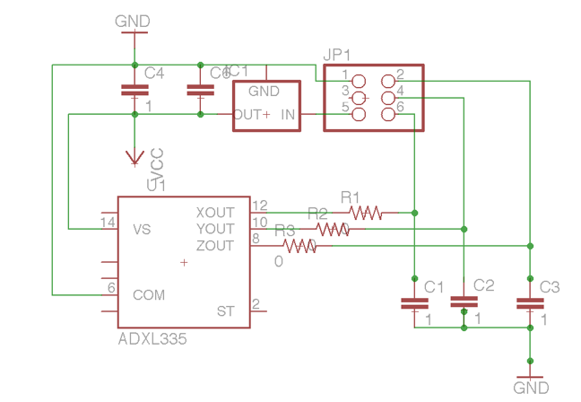
The
ADXL335 has resistors built in resistors so technically I don’t need the ones
in the above diagram, and they are zero ohm. I included them on the advice of a
former technical director at RIM who said she always made provision for them,
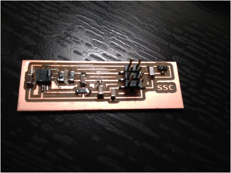
so she could tweak the filter later if necessary. Used a 3.3V Voltage Regulator to adjust
from the 5V that is supplied via USB.
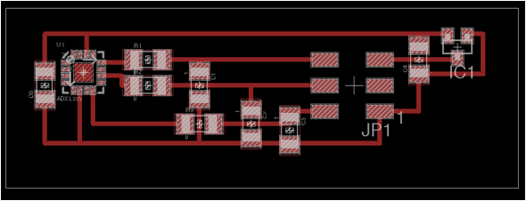
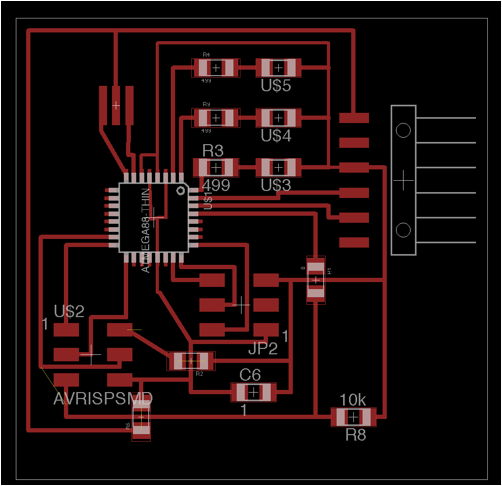
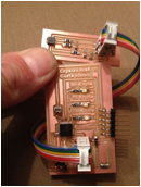
I
spread the layout a little to fit in some text on the main board
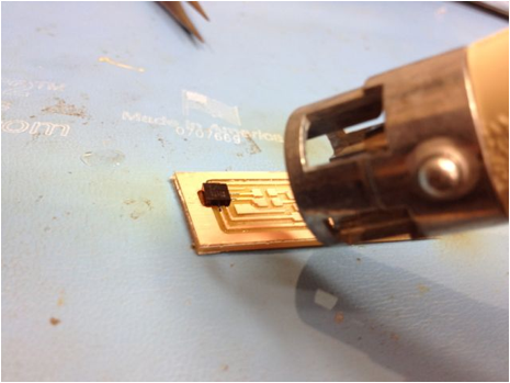
The ADXL335 is tiny, with the pads entirely ventral.
Neil’s advice was to solder the traces underneath, then use the heat gun. This was really hard in practice
Board took code, after fiddling with the make file (AT Mega 328p – I was missing the p). Unfortunately there was a puff of smoke from the voltage regulator when I plugged the accelerometer board in. I’m suspecting my cable. Not sure whether the Accelerometer is still functional.
The embedded code has the LEDs flashing on a loop with a delay.
Next steps:
Make a working accelerometer board, consider using the single axis accelerometer which has a higher voltage range, and fewer outputs. Technically I only need one angle, but would then need to make sure the alignment was fore and aft. This would free up an input on the ATMega for windspeed. Ideally I would like this to output to an LCD display