Week 1: Computer-aided Design (CAD)
Ideation of Potential Final Project
Our very first assignment for "How To Make (almost) Make Anything" was to plan, draw, sketch, model, simulate, and/or animate a potential final project.As of week 1, I am thinking about making a third hand. Speaking about "third hands", there are a wide variety of things that you can imagine from it. For example, one might think of a robotic arm that allows you to hit a home run while playing baseball. Others might think of it as a mechanical arm that helps hold your laptop while standing.
My interpretation of it is something that can remotely transmit the sense touch of objects. The following sketch shows the basic concept.
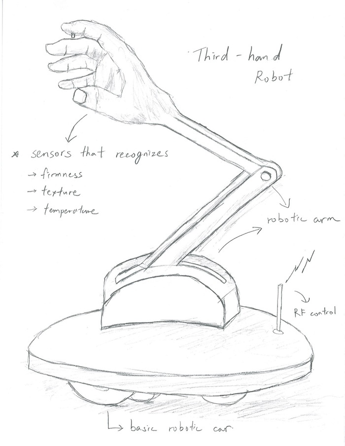
It is a remote controllable robot with an arm and a hand. On the hand, there are sensors that digitize the sense of touch from the following aspects.
- Texture (from smooth to rough)
- Temperature (from hot to cold)
- Firmness (from soft to hard)
While there are many ways how we can remotely feel, understand, and spread visual and auditory components of the physical atmosphere (e.g. live video streams and telephones calls), this "third hand" represents one way of how we can transmit and share tactical sensations to someone nearby and/or faraway.
Approach
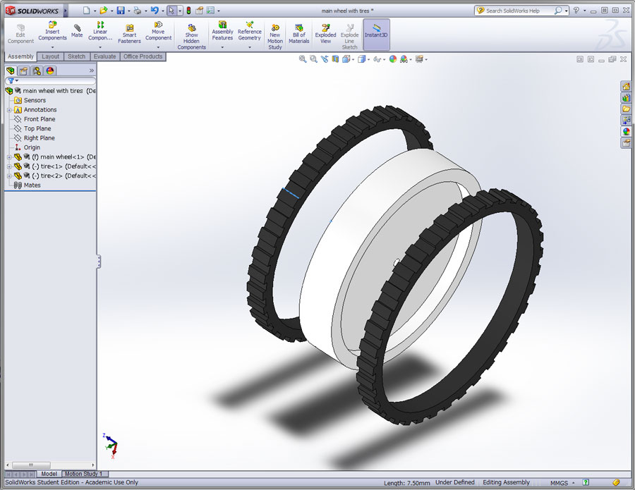
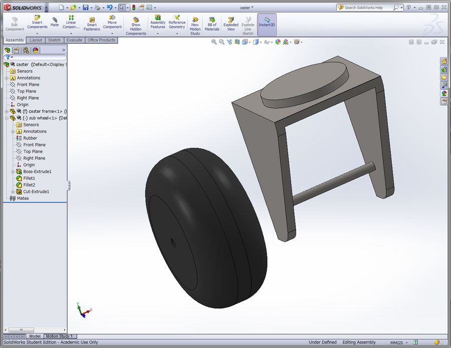
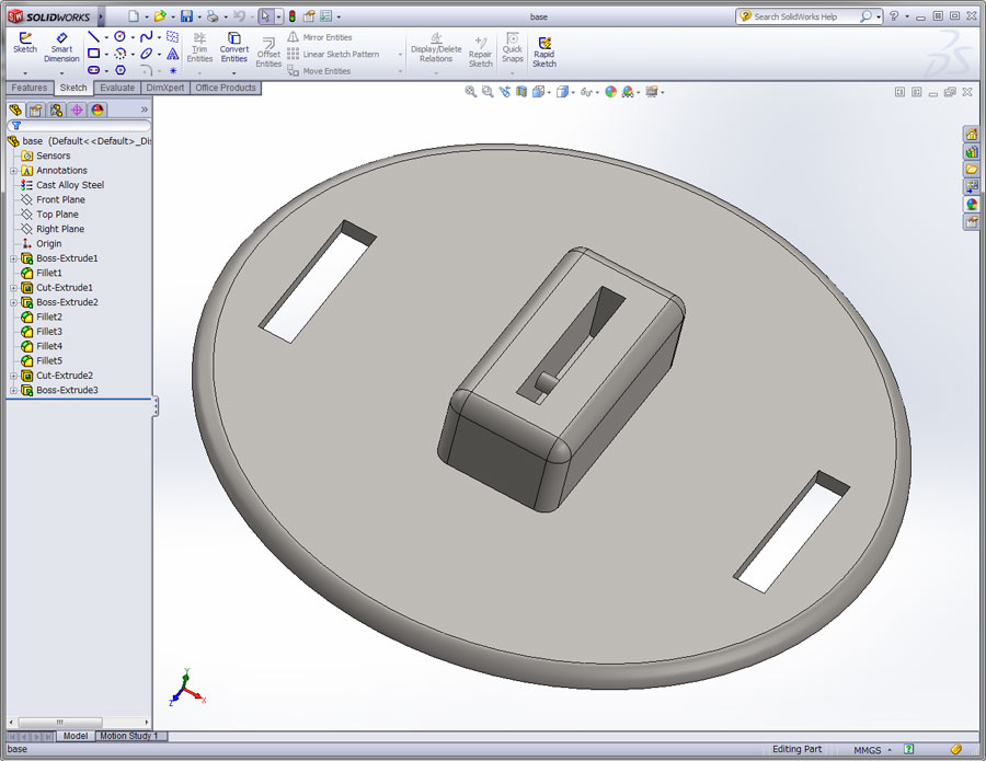
First of all, the base consists of 2 main wheels with motors, and 2 free casters. The motored wheels placed along the diameter enable spin and turn, as well as going back and forth. As for the arm, servos would control the 2 joints. Finally, as for the hand, it would be equipped with a camera for sensing the texture, a temperature sensor, and a hardness sensor (durometer or pressure sensor).Since I have no background in mechanical engineering or electrical engineering, I still have a long way to go in figuring out which types of sensors might be the best to achieve the goals. The approach towards this project is to be updated continuously.
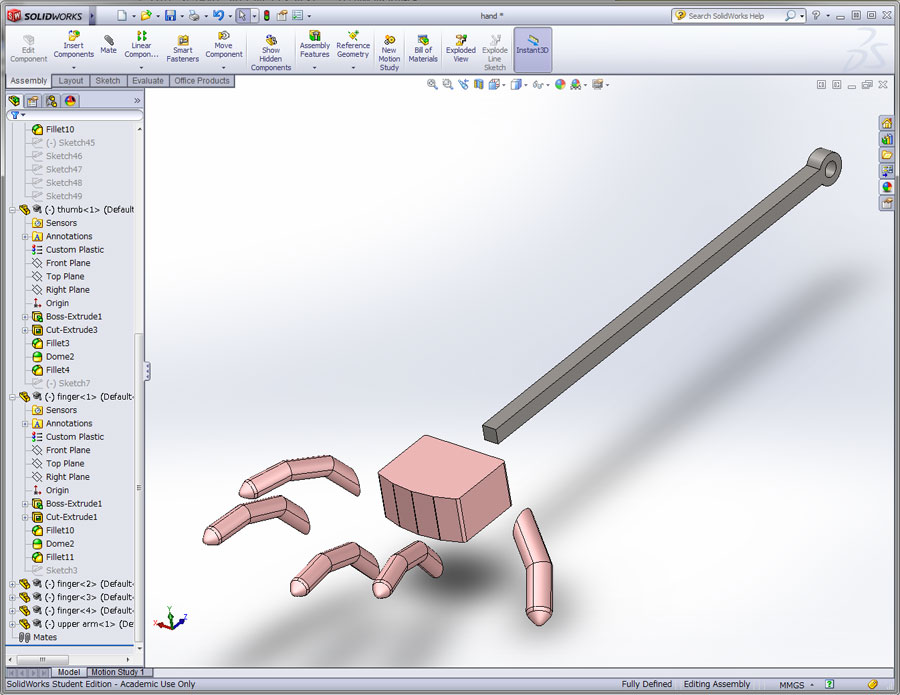
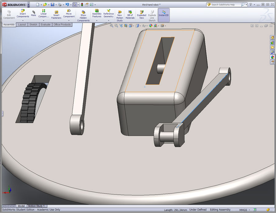
CAD and 3D Modeling
Based on the initial visualization of my idea on a piece of paper, I decided to play around with CAD, and try to create a 3D model of this machine. As this was first ever time to deal with 3D modeling, I decided to first try out both Autodesk Inventor and Solidworks.After running a few online tutorials of both Inventor and Solidworks, I figured Solidworks was more comfortable to use. Both programs are merely the same in terms of basic functionalities. However, I personally felt that the UI of Solidworks was more simple and intuitive, compared with Inventor.
I spent entirely 2 days trying to figure out the ABC’s of Solidworks, and how 3D design and modeling is done. There still is long way to go, but I was able to learn how to model machine parts by extruding or cutting geometric attributes. I also learned how to “mate” the parts together and assemble the final product.
|
|
|
|
|

|

|
|
After the design and assembly was done, I created an animation of how this thing would work. The following video shows the final outcome of this model.
Conclusion
As an overall impression of Solidworks and 3D modeling, I found it extremely FUN and exciting! The assembly process reminded me of the old days when I used to be a little kid building plastic models of planes and cars. However, there are a few things that I struggled.- It was extremely important to have a nice 3-button mouse with a physical scroll wheel. Dealing with Solidworks using the Apple Magic Mouse was a terrible pain.
- When designing parts, I realized the importance of making sure part files were out of the sketch view, before saving. I was confused when it was not possible to “mate” sketch attributes together, when the sketch view was left editable.