Week 3: Electronics Production
Overview
The third assignment of the semester was to make our own "FabISP", which is a in-circuit AVR programmer. This week, I learned how to...- Mill circuits on a PCB board
- "Stuff" the board with tiny componentes using a soldering iron.
- Burn a program on to your own piece of hand-made hardware.
- Create a press-fit acrylic case for the FabISP (EXTRA)
Milling the Circuit Board - First Attempt
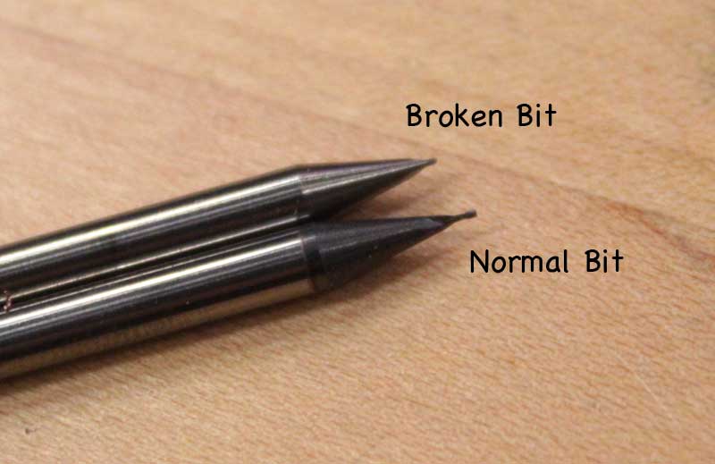
The first step of this assignment is to mill the PCB board and create circuit paths. We used the Roland MODELA, which is a small scale CNC milling machine along with the Fab Modules. The original tutorial (along with other materials) for making the FabISP may be located here.For tracing the paths, we used a 1/64 inch bit, and for cutting out the board, we used a 1/32 inch bit. Obviously, the tiny bits may break very easily, and must be handled with care. This was the first mistake. It seems I "dropped" the bit on the board when setting the Z-height, which probably damaged the bit. A few moments lateri after starting the milling process, the drill bit was gone.

|
|
Milling the Circuit Board - Additional Attempts
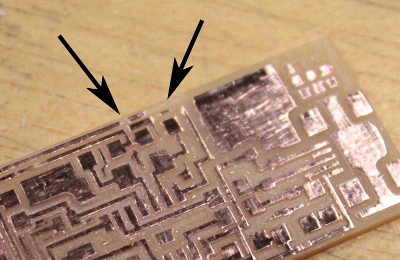
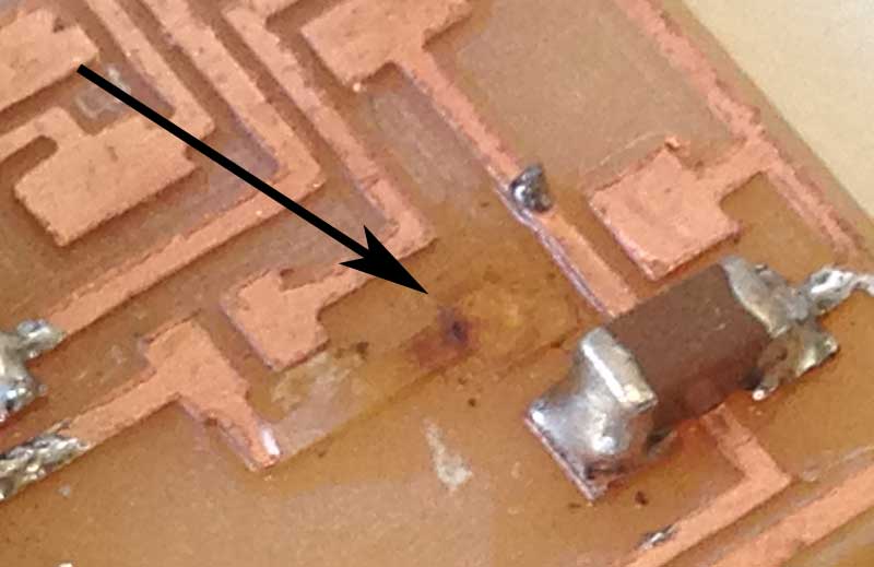
After learning the lesson of handling the bits with care, I did three aditional tries, which all happen to fail. The causes of these failures were due to...- Bad Z-height and/or depth setting, which gave me imcomplete traces
- Deburring the edges with too much force, which tore some of the wiring copper off the board
- Having the wrong offset values (had 1 instead of 4), which gave me barely any space for soldering
|

|
Milling the Circuit Board - Final Attempt
In order to overcome all the causes of failure, I used the following methods and settings.- Adjust the Z-height at the center of the board, as well as all corners
- Offset: -1 (to remove all unnecessary copper and make it look nice)
- Speed: 3.4 mm/sec (since the bit was relatively new)
- Depth: -0.15 mm (traces) / -2.1 mm (outline)

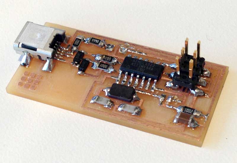
Soldering the Components
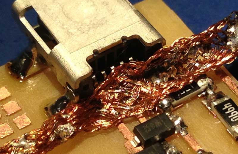
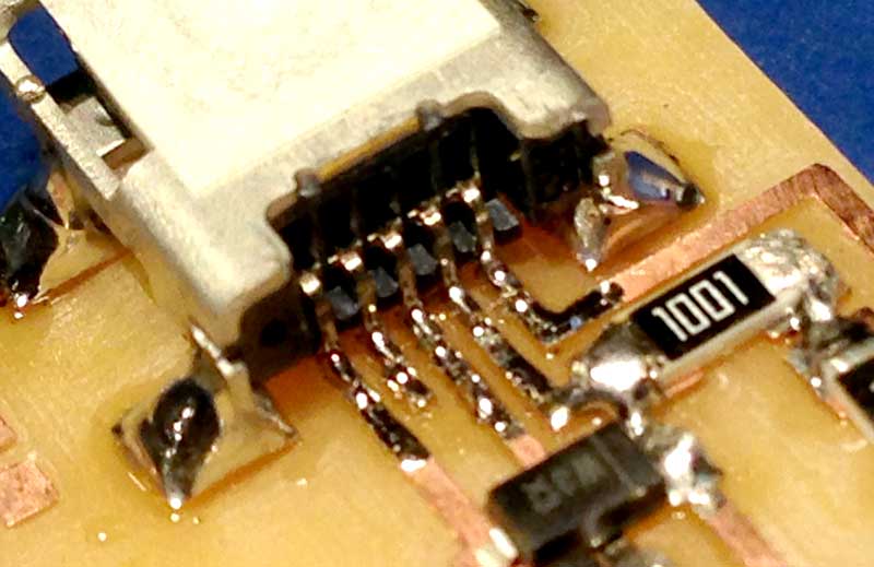
The next step was to solder all the components on the board that I just made. There were 19 parts in total, including the cables, connectors, and jumpers. For the jumpers, I used 0 ohm resistors.I took Neil's advice of applying a dab of solder on small wirings, and removing the excess using a solder remover. This method worked out perfectly, and I was able to solder extremely small wirings together fairly easily.
|
|
|
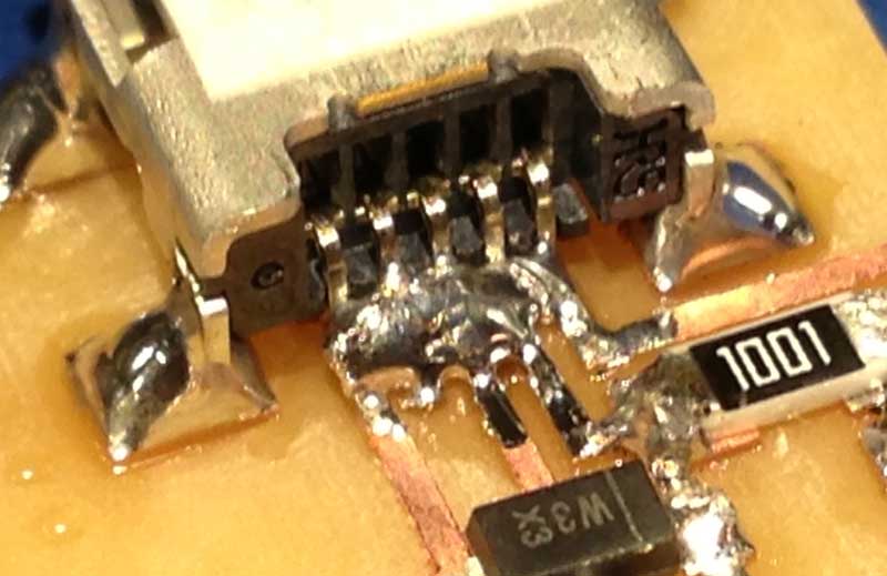
The first few parts, including the microchip and USB connectors went just fine, until I came across one resistor. Apparently, I failed to align the resistor to the wires. In order to fix that, I heated the solder and tried to lift it off. However, I pulled a little too strong while the solder was not yet fully wet. This forced the copper wiring to come off the board and eventually got torn.
For the sixth time, I went down to the machine shop and milled a new board. Luckily, thanks to all the lessons I learned, I was able to mill out a board smoothly in no time.
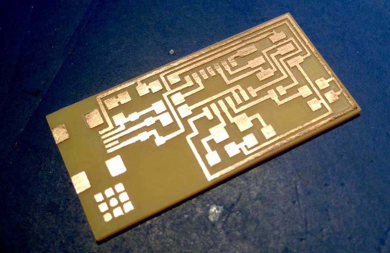
I spent about another hour or so soldering all the parts together on the new (6th) board. Finally, after all the mistakes I have made, I was able to complete the circuit board itself.
Burning the Firmware
Now that I got my self a board, the next step was to burn the firmware on to the FabISP and desolder the two jumpers (SJ1 and SJ2). When the two jumpers are shortened, the board becomes programmable by other programmers. Otherwise, it acts as a programmer itself.I normally use Mac OS X, so I went to this website and installed their "CrossPack for AVR Development" package. This package installs pre-compiled versions of all the necessary libraries and utilities to develop software for the AVR microcontroller.
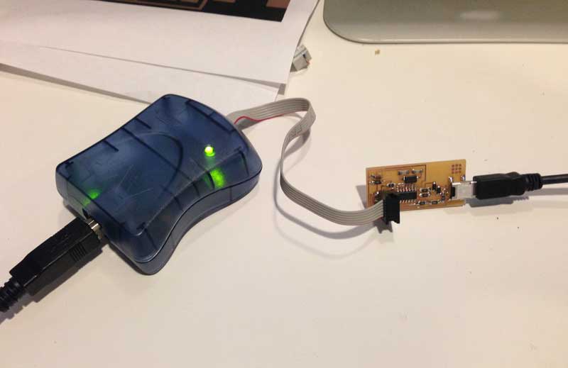
After getting the firmware source files, I connected my FabISP to AVRISP mkII programmer, and prepared to burn the firmware. If the LED on the mkII turns green, it means that it has discovered an AVR chip and is ready to burn something on it.
Running "make hex", "make fuse", and "make program" in order should cross-compile the firmware and burn it on the chip. However, when I executed "make fuse", it gave me the following error.
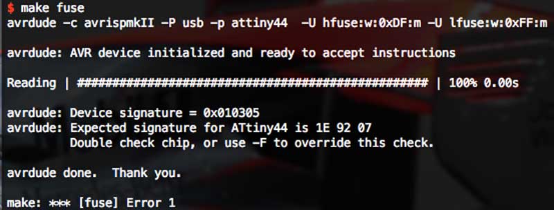
I first thought that this was due to some hardware error on the board. I tripple checked the board for any shortened circulates or bad solders. However, I couldn't find anything wrong. After consulting to google for a while, I came across this thread. According to the information in this thread, device signiture errors may occur if the ISP frequency is too high.
As for the solution, I edited the Makefile (line 16 to 22) in the source package and added a "-B5" option in the avrdude command under "make fuse". This option sets the ISP bit clock period to 5 microseconds (200 kHz).

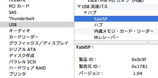
This successfully solved the problem. I was finally able to program the board, and see the FabISP from the list of device in Mac OS X. After verifying the board being recognized properly, I desoldered the jumpers (SJ1 and SJ2) from the board.
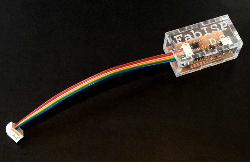
Making a FabISP Case (EXTRA)
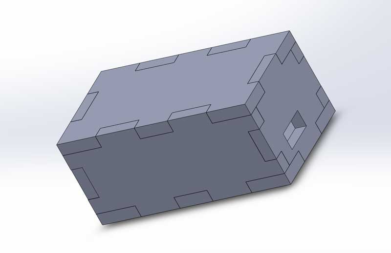
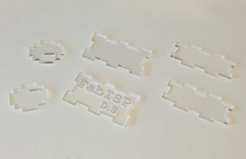
The assignment was completed. However, I wanted to add my sauce to it, and decided to create a press-fit acrylic case for my FabISP.As usual, I turned to Solidworks and designed the parts. After designing the parts, I picked up a scrap piece of clear 1/8 inch acrylic and laser-cut the parts. I also laser-engraved "FabISP" along with my initials ("D.S."). Feel free to download the outline of the parts below.
|
|
When I tried to assemble the parts, I found that the joints were too loose to hold the parts together.

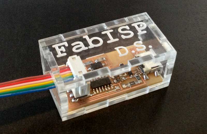
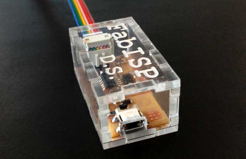
So I adjusted the part dimensions and made the length of the gaps 0.5 mm shorter than the length of the stub. I cut out the parts again, and a cute case with very nice press-fit joints was created.
|
|