Week 8: Computer-controlled Machining
Overview
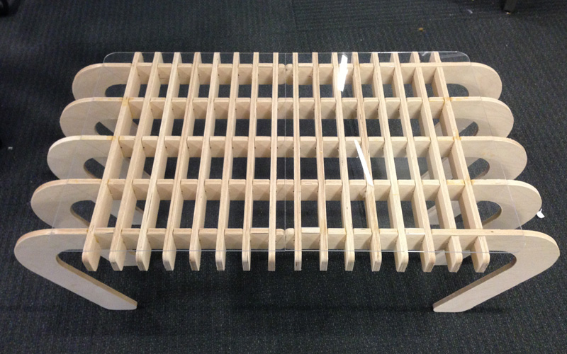
The 8th assignment of the semester was to create something BIG, using computer-controlled machining tecniques. I decided to make a two-way table which functions both as a coffee table and a bed desk. This week, I learned how to...- Use the ShopBot (large-scale CNC milling machine)
- Design and build wooden furniture
|
|
Concept
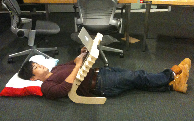
The idea came to mind when I was using my computer while in my bed. Using computers in bed could be challenging in many ways, since you have to be positioned in a awkward way to properly use the device.So I decided to make a bed desk for my laptop. However, I didn't want to make something that would be large enough to cause trouble while not in use. So I thought about ways how I can make use of a bed desk for other things.
An idea came up when I was having dinner on my work desk. I wasn't able to feel relaxed because of the computer and the office chair. It made me feel as if I was still at work. I realized I needed a coffee table to simply enjoy food and drinks in a relaxed fasion. If I needed both a bed desk and a coffee table, I figured I should combine the two and make something that would satisfy both needs.
Design
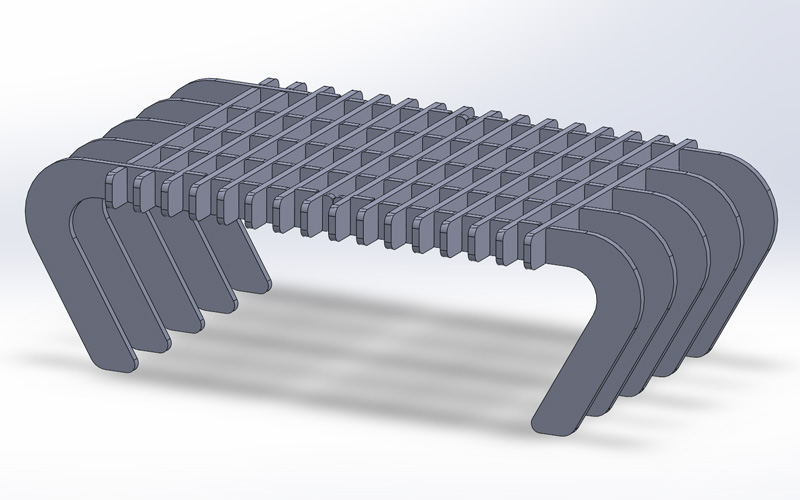
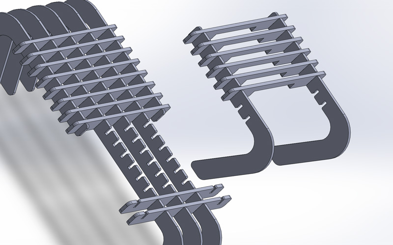
As for the material, we were each given a 4 ft x 8 ft x 1/2 inch MDF board. Using the ShopBot, we were to machine this material and create parts for something BIG.I used Solidworks and first designed a coffee table with press-fit joints. I then made certain portions detachable to use as a bed desk when necessary.

|
|
|
In order to support the laptop in bed desk mode, I also made a one replaceable piece which is slightly higher than the table top surface height.
I also designed acrylic table top surfaces, which make it more useful when using the my table as a coffee table. After the design was completed, I exported the outlines into DXF files. The outline files may be downloaded below.
Creating The Toolpath
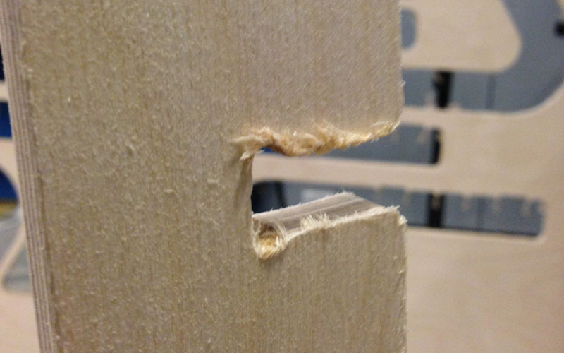
The ShopBot is a gigantic CNC milling machine with a work area of few meters. When creating the toolpath for the Shopbot, I used a software called PartWorks. I first imported the DXF file with the outline, and created "T-Bone" fillets. Since the ShopBot uses drill bits for milling the traces, it cannot create sharp edges. Therefore, "T-Bone" fillets must be made for the drill bit to successfully pass through the edges while maintaining right angles.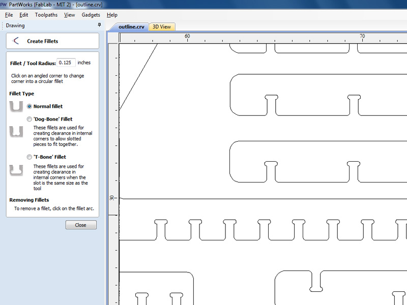
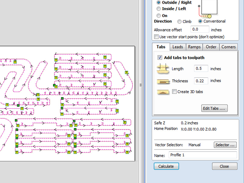
After creating the fillets, I created a "Profile Toolpath" for cutting out the parts. I added an additional 0.1 inch to the material thickness to cut it all the way through. I also added 2 tabs for each part to hold it in place after cutting the trace.
As for the ShopBot settings, I used the following parameters.

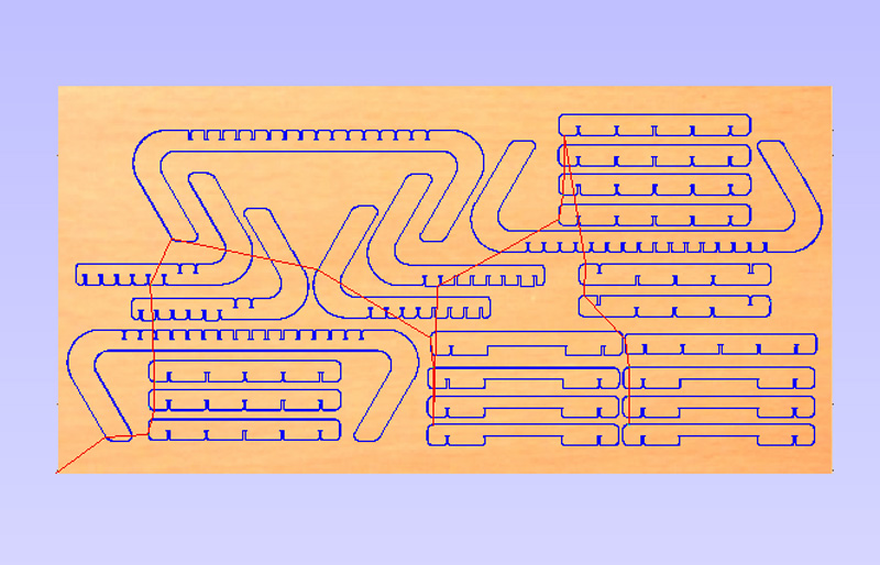
In order to cut the traces, the toolpath must be exported as a SBP file, which is a sequencial representation of the toolpath in 3 axis coordinates. Before exporting the toolpath, I verified it in PartWorks and made sure there was no issue.
I thought everything was all set at this point. However, Tom advised that I get a plywood for my parts, since the provided MDF board would not work with my design. According to Tom, my parts were too skinny for the MDF to hold itself together. So I got my own plywood over the weekend.
Preparing the ShopBot
Before running the traces, the material had to be screwed down to the sacrificial layer. The drill bit also had be firmly attached to the spindle as well, and all 3 axises had to be positioned at zero. Thanks to Tom's help, I was able to do this smoothly and was ready to run the job in no time.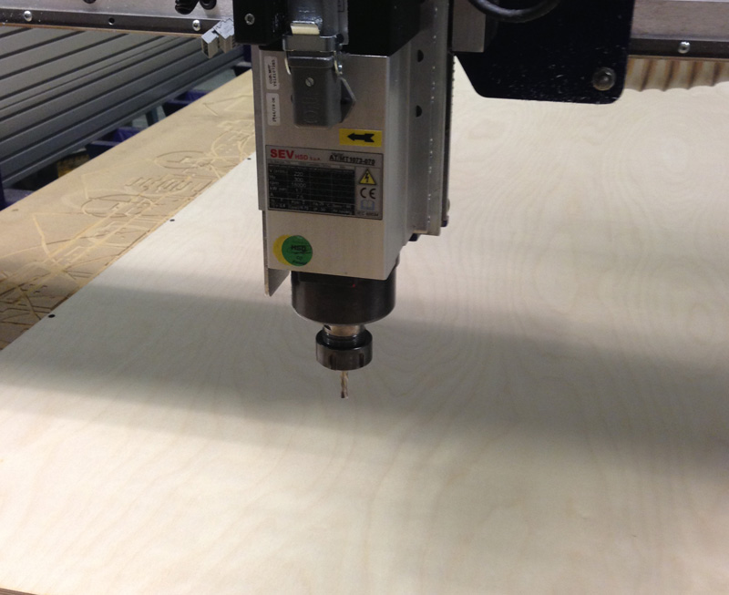
I then imported the SBP file and inserted the safety key into the control box. I also turned the vacuum cleaner on and pressed the switch to turn on the spindle. the vaccum is running, and the spindle is turned on.
Milling the Traces
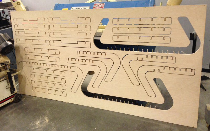
After double checking I did everything I was supposed to do, I pressed the start button and ran the traces. It took roughly 30 minutes to complete the entire job.Deburring the Edges
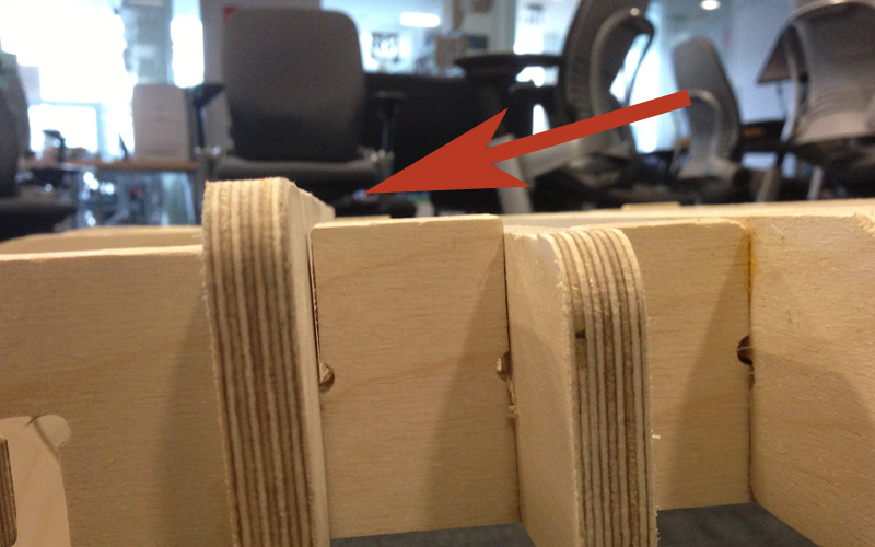
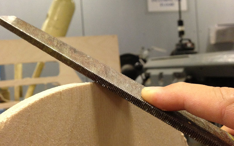
The milling job was successfully complete, and I removed the material from the sacrificial layer. Thanks to the tabs, the parts were able to stay in place after being cut through. After taking each part off the board, it was time to deburr the edges. I used a hand file, as well as chisel and a sand belt for this.
|
|
|

|
Cutting Out the Table Top Panel
The deburring took a while to complete, but eventually, I was able to complete fabricating all 24 parts of my table. It was now time to use the laser cutter to cut out the table top panels from 1/8 inch acrylic boards.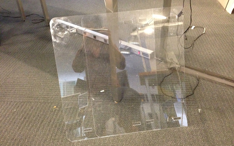
Assembling the Table
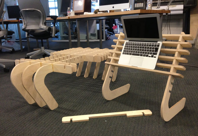
I now had all 26 parts that make up my multi-functional table. When putting together the press-fit joints, I realized the gaps were slightly too wide for firm connections. Therefore, I applied a little bit of wood glue on the fixed joints to make everything more stable.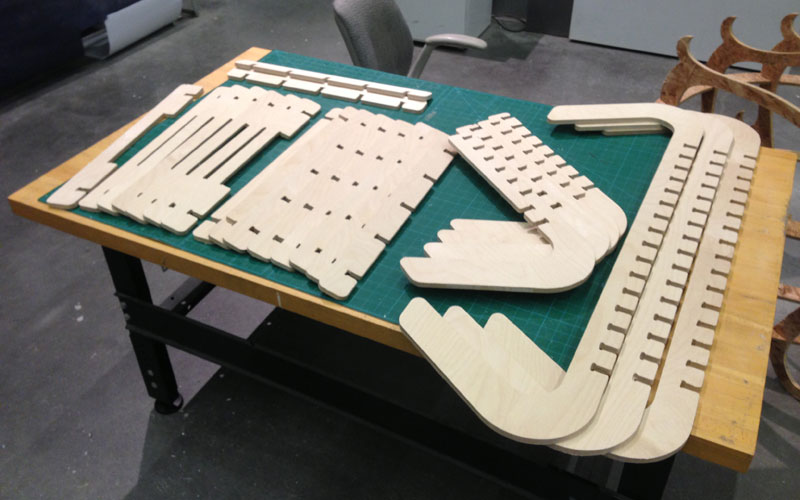
After everything was done, I had a nice two way table that functions both as a coffee table and a bed desk!

|
|
Downloads
You can download the outline files for the parts of the table here.- Table Parts (DXF Files)