This week assignment was to redraw the echo hello-world board, add at least a button and LED (with current-limiting) resistor.
I started by assisting to the tutorial on EAGLE. I download the program and the fab library.
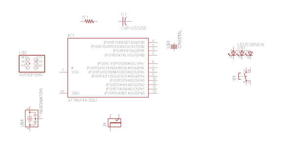
Once I finish this, I place the different parts on the board to start the schematic design. It is my first time designing an electronic board, so I hope I do it all right:
Then I start connecting different parts with wires. I will first copy the connections in the echo hello-world board to learn the way I can connect parts together:
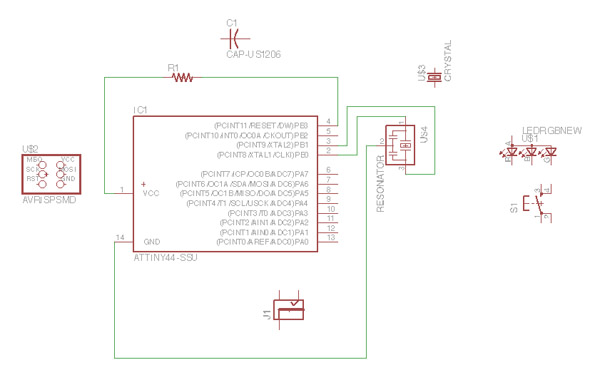
The first board before adding LED and button looks like this. The connector is not right as I could not find the 1x6 FTDI connector in a first moment:
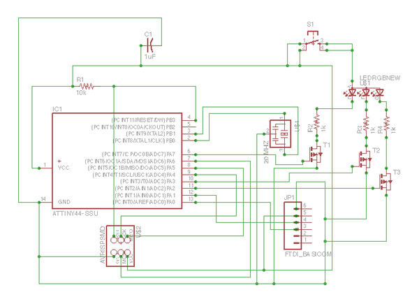
I finally find the FTDI connector in the library with the help of a classmate. I change the connector and introduce the button and the LED. I decide to use a RGB LED so I will also need three transistors and three resistors (one for each color R-G-B). Once I finished, the schematic design looks like this (I am not very sure if things are connected correctly):
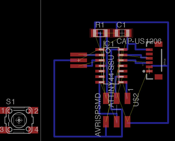
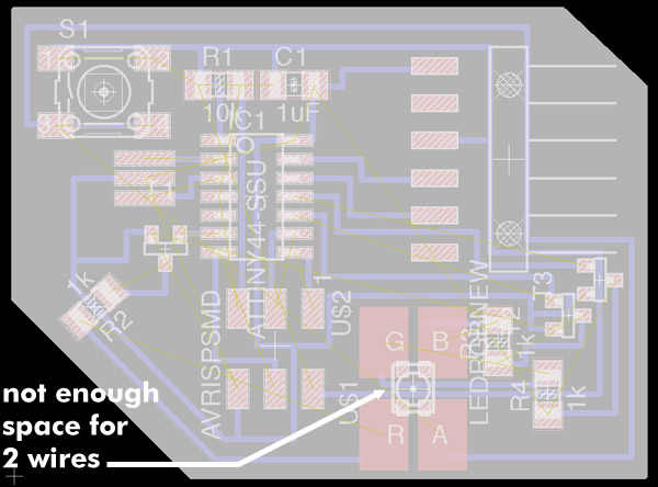
Once I finish the schematic, I design the board. I have some problems introducing the transistors and resistors for the RGB LED, but I manage to connect them all by bridging the resistors over the wires that interrup the connections. Once I finish the board I try milling it, but the wires are too close to each other in some places and they join when I generate the traces... so I need to reconfigure the design!
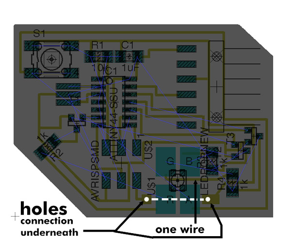
I reduce the wires under the LED to one single cable, but then the VCC wire is interrupted. After trying to connect it in different ways I decide to make two holes so I can pass the wire underneath the board to 'jump' the R and A sockets of the LED:
Once I finish this final adaptation of the design, I start milling in the Modela, but the 1/64 endmill is not working correctly, so I have to changeit and start again!
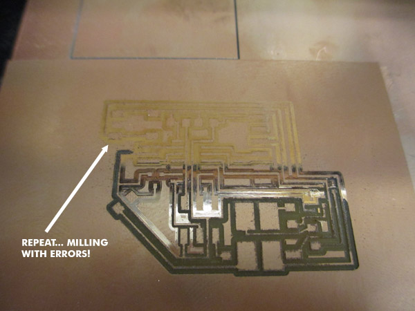
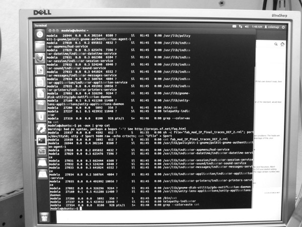
I am not able to erase the job so I have to wait for the Modela to finish 'milling':
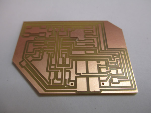
Once I change the endmills it works much better and the board before stuffing looks like this:
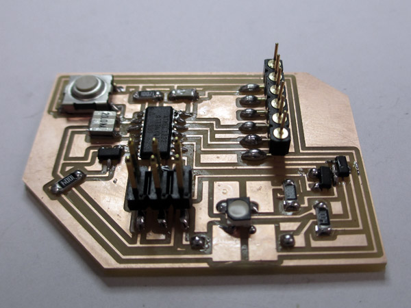
Once stuff the parts the board looks lke this.... I HOPE IT WORKS AND THAT I AM ABLE TO PROGRAM IT... I have no idea of programming!!
Top view:
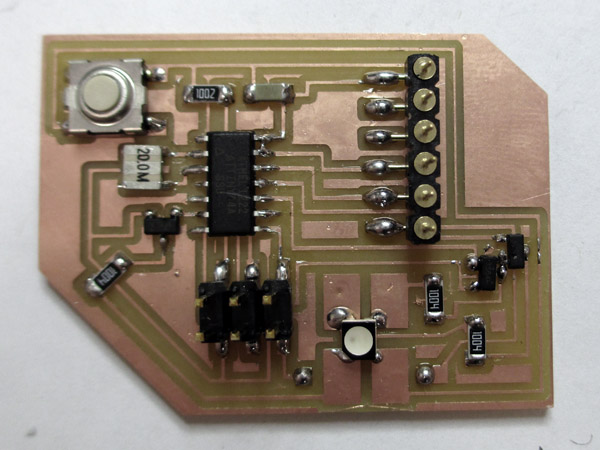
:)