3D Scan Using Minolta & GeoMagic


I. Turn on Minolta
-
• Remove lens cover and laser cover1
-
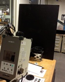
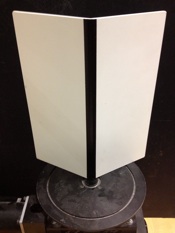
• Place black poster behind platform2
-
• Flip switch on minolta to turn on
-
• Wait some time to initialize
-
• when Prompted "Please open Laser Barrier" Hit any key3
-
• Open GeoMagic software
-
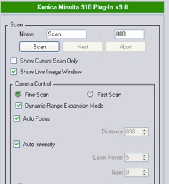
• Navigate to Plugins → Konica Minolta 901 Plugin v9.0
-
• when Prompted "Do you want to calibrate the turntable axis"
Select No -
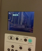
• Check minolta is displaying “Remote”4
1 medium lens is best
2 minolta does not capture black very well
3 already did with first step
4 if not, reboot computer
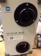


lens
laser

black
poster

Remote
II. Calibrate Minolta
-
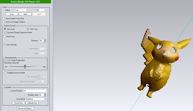
• Click “Show Live Image Window” in the left side Scan panel
-
• Click “Enable Streaming Video” to see if capturing
-
• Place chart on the platform (nicely centered)
-
• Uncheck “Enable Streaming Video”
-
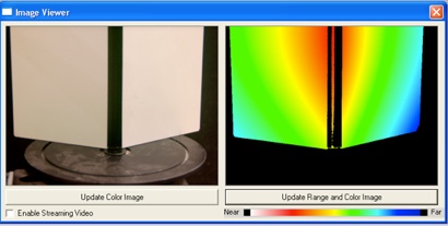
• Click “Update Color Image”
-
• Wait, then Click “Update Range and Color Image”
-
• Check image to see the chart is colored within spectrum.
-
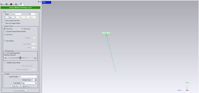
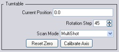
• Click Calibrate Axis under Turntable panel
-
• when Prompted "Please set the chart on the turntable" Click ok
-
• Check to see a TurnTable Axis in your 3d environment
III. Test Scan of Piece


-
• Remove chart and Place piece on the platform
-
• Back in the “Show Live Image Window”, Click Enable Streaming Video
-
• Click “Update Color Image” and Click “Update Range and Color Image”
-
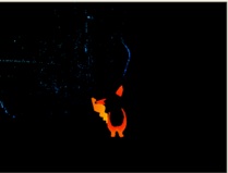
• Check image colored within spectrum, Aim for middle depth to be yellow
-
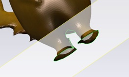
• If images look like example 1 or example 2, then autofocus didn’t do a
good job, so now need to manually set the focus -
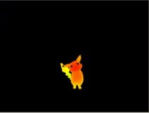
• Uncheck autofocus, change the “Distance” up or down incrementally
(by 10’s) then Click “Update Range and Color Image” -
• Repeat until piece is colored nicely within spectrum like example 3
Example 1 (Bad) Example 2 (Better but Bad) Example 3 (Good) -
• Click “Scan” button for a test scan
-
• Check that scanned image looks good, okay if there is outer noise


IV. 360 Scan of Piece

-
• Under the Turntable panel
-
• Current position should be 0.0
-
• Set “Rotation Step” to 45 degrees
-
• Set MultiShot for “Scan Mode”
-
• Click Next, the platform will rotate 45 degrees and take another scan
-
• Repeat until “Current Position” does a full 360
-
• once completed, Click Ok button at the very bottom
-
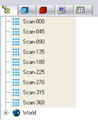
• the left panel should display a list of scans and a solid piece (w/ noise + holes)
-
• Navigate to File → Save As a “Wrap File .wrp”


V. Cleaning Scan

-
• Click and Drag to highlight a noisy region then hit delete key
-
• Repeat until no visible noise
-
• make sure to rotate around using middle button of mouse
-
• to deselect a highlighted area, right click and select clear all
-
• Select all scans on left panel by holding down shift
-
• Navigate to Points → Reduce Noise, Click Apply and Ok
-
• Select all scans, Navigate to Points → Merge, Click ok
-
• Select the merged file at the bottom of scan list
-
• Navigate to Polygon → Clean
-
• If desired, you can reduce the noise again on the merged and cleaned file
before cleaning after cleaning
-
• SAVE


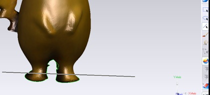
VI. Filling in Holes

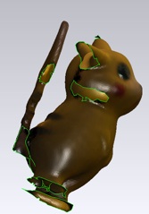
From the front view, the piece can seem deceivingly whole,
but once you rotate, you will notice holes everywhere.
-
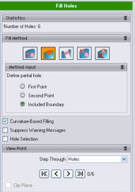
• Navigate to Polygon → Fill Holes
-
• Under Fill Method, select the second “Partial Fills” option
(Note: the first all “Fill” option is a little dangerous in that if there are complex and large areas it can stall the computer forever or make some areas really flat and not nicely curve) -
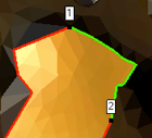
• Define the desired boundary by clicking on the outline your first, second, and third points for the boundary
before fill hole after fill hole -
• Click Ok at the bottom to save this filled hole
-
• Repeat filling holes until all are sealed
-
• Under “View Point,” Step Through Holes can auto direct
you to holes


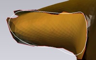
VII. Filling in Holes - Advanced (Smooth Boundaries)

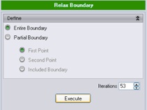
VIII. Filling in Holes - Advanced (Close w/ Planes)

-
• Navigate to Boundaries → Relax
-
• Select boundary to relax
-
• Increase (or decrease) the iteration to make the white boundary become smoother
-
• Click execute and Click ok
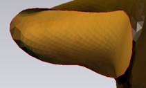
before after

-
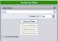
• Navigate to Polygons → Section by Plane
-
• Change “System Plane” to “Line”
-
• Select the line tool
-
• Select and Drag a straight line over desired region
-
• Rotate the piece and Move the “Position” until at a good intersection
-
• Click Intersect plane, Click Delete section, Click Close intersection, Click Ok


IX. Saving out .STL

-
• Right click on the Merge file
-
• Click save
(Note: if it complains about the model not being water tight then you need to re-look at holes) -
• Save as type STL binary File .stl
-
• To reduce file size, Navigate to Polygon-→ Decimate
-
• Set "Reduce to Percentage" to 50%
-
• Click apply if no important features are lost
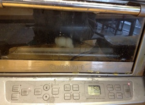
X. De-waxing

After your piece is printed out, it will need to be de-waxed by being heated in a small oven
-
• Set the oven’s mode to Bake
-
• Set the temperature to 150
-
• Hit Start
-
• Wait until all the wax melts off (~40minutes)